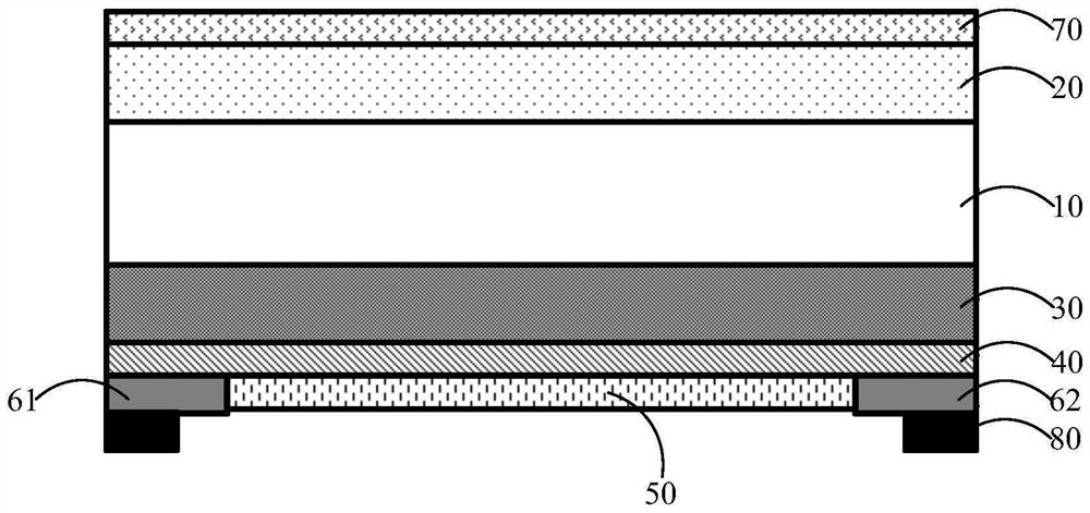
Optical filter

An optical filter and dielectric film technology, applied in the optical field, can solve the problems of poor radome adaptability, easy to be affected by ice, snow, fog and frost, poor anti-interference ability of optical signals, etc. and impaired imaging capabilities, excellent optical properties, reduced light interference

Pending Publication Date: 2022-04-26
ZHEJIANG CRYSTAL OPTECH
View PDF0 Cites 0 Cited by
  • Summary
  • Abstract
  • Description
  • Claims
  • Application Information

AI Technical Summary

Problems solved by technology

[0003] Ordinary radomes are poorly adapted to cold and harsh environments, and are easily affected by ice, snow, fog and frost in cold environments, so radomes with heatable functions emerge as the times require
In order to solve the above problems, the prior art provides a radome heated by heating wires located on the front of the front cover. However, the existing radomes heated by heating wires will affect the penetration of the lidar and the laser The radar imaging effect cannot meet the low reflectivity requirements of the lidar cover, and its ability to resist optical signal interference is poor

Method used


Image

  • Optical filter
  • Optical filter
  • Optical filter

Examples


Embodiment Construction

[0029] The embodiments described below represent information necessary to enable those skilled in the art to practice the embodiments described, and show the best mode of embodiment in practice. After reading the following description with reference to the accompanying drawings, those skilled in the art will understand the concepts of the present invention, and will recognize the application of these concepts not specifically presented herein. It should be understood that these concepts and applications fall within the scope of the present invention and the accompanying claims.

[0030] It should be understood that, although the terms first, second, etc. may be used herein to describe various elements, but these elements should not be limited by these terms. These terms are used only to regionally divide one component from another. For example, without departing from the scope of the present invention, the first element may be referred to as a second element, and similarly, the se...


PUM

PropertyMeasurementUnit
thicknessaaaaaaaaaa
thicknessaaaaaaaaaa
refractive indexaaaaaaaaaa

Abstract

An optical filter relates to the technical field of optics. The light filter comprises a substrate, a first antireflection film arranged on one side of the substrate, and a medium black film, a transparent conductive layer and a second antireflection film which are sequentially laminated on the other side of the substrate, wherein a positive electrode and a negative electrode which are positioned on the transparent conductive layer are plated between the transparent conductive layer and the second antireflection film; wherein the first antireflection film comprises a first film stack, a second film stack, a third film stack and a fourth film stack which are sequentially stacked on the substrate; the dielectric black film comprises a first film layer, a second film layer and a fifth film stack which are sequentially stacked on the substrate; the first film stack, the second film stack, the third film stack, the fourth film stack and the fifth film stack are respectively formed by stacking at least three dielectric film layers, and the refractive indexes of two adjacent dielectric film layers are different. When the optical filter is used as a laser radome, the optical filter can adapt to a cold environment, optical signal interference can be reduced, and optical performance can be improved.

Description

Technical field [0001] The present invention relates to the field of optical technology, in particular, to a filter. Background [0002] With the rapid development of autonomous driving in the automotive industry, the application of lidar for adaptive cruising has become more and more extensive, and the importance of radomes installed in front of lidar as a protective function has gradually become prominent. [0003] Ordinary radomes are less adaptable to cold and harsh environments, and they are susceptible to ice, snow, fog and frost in cold environments, so radomes with heating functions came into being. In order to solve the above problems, the prior art provides a radome heated by a heating wire located on the front of the front cover, however, the existing radome heated by the heating wire will affect the penetration of lidar and the lidar imaging effect, and can not meet the low reflectivity needs of the lidar, and its anti-light signal interference ability is poor. Cont...

Claims


Application Information

Patent Timeline
Patent Type & Authority Applications(China)
IPC IPC(8): G02B5/20G02B1/115H05B3/20H05B3/03
CPCG02B5/208G02B1/115H05B3/20H05B3/03
Inventor 尧俊卢仁吴永辉张睿智王彦鹏王建晖羊彦刘风雷
Owner ZHEJIANG CRYSTAL OPTECH
Why Eureka
Try Eureka