High-temperature gas-solid mixed phase separation equipment

A technology for separation equipment and mixed phases, applied in separation methods, dispersed particle separation, combined devices, etc., can solve problems such as high-temperature plastic deformation, metal oxidation, and failure of separation equipment, and achieve the effect of avoiding high-temperature oxidation

Active Publication Date: 2022-04-29
QINGDAO YUNLU ADVANCED MATERIALS TECH CO LTD
View PDF11 Cites 0 Cited by
  • Summary
  • Abstract
  • Description
  • Claims
  • Application Information

AI Technical Summary

Problems solved by technology

Metal materials commonly used in separation equipment will have problems such as metal oxidation and high-temperature plastic deformation under such high-temperature long-term action, and after the high-temperature gas-solid mixed phase containing molten particles enters the commonly used gas-solid separation equipment, the molten particles will be adsorbed, sticky, etc. Sticking to the inner wall of the separation equipment, with the cooling and solidification of the molten particles, the particles and the inner wall of the equipment are integrated, and the solidified particles and the molten particles are mutually adsorbed, sticky, cooled and solidified, and finally on the inner wall of the equipment Large accumulations are formed on the surface, destroying and blocking the internal structure of the separation equipment, resulting in failure of the separation equipment

Method used


Image

  • High-temperature gas-solid mixed phase separation equipment
  • High-temperature gas-solid mixed phase separation equipment
  • High-temperature gas-solid mixed phase separation equipment

Examples


Embodiment 1

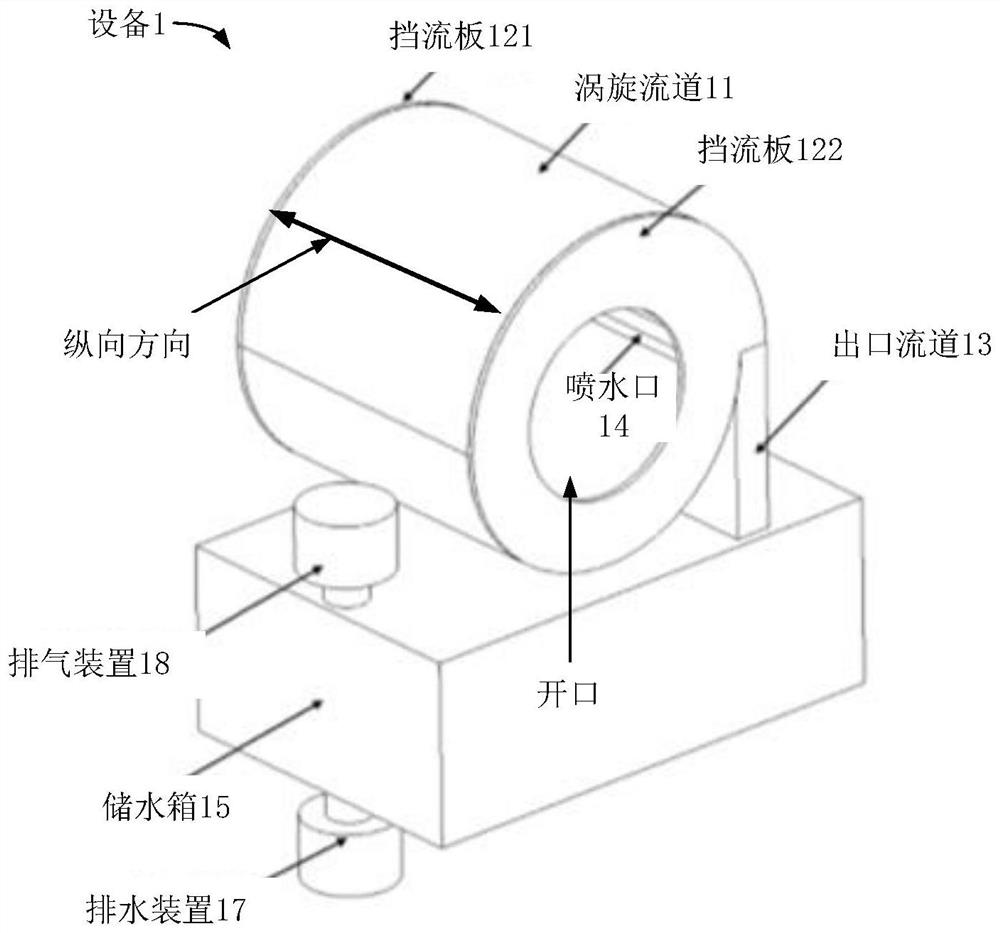
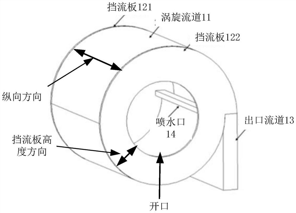
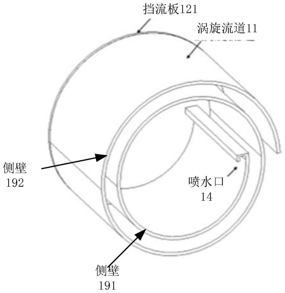
[0094] use Figure 1A In the shown device, the number of turns of the side wall included in the vortex channel 11 needs to be ≥1. Wherein, the more the number of turns of the side wall included in the vortex channel 11 is, the higher the separation efficiency of the gas-solid mixed phase is, and the better the cooling effect is. The equipment parameters and test results of the vortex channel 11 with different turns are shown in Table 1.

[0095] Wherein, the radius of the innermost circle of the vortex channel 11 is 200 mm, the wall thickness of the vortex channel 11 is 10 mm, and the distance between adjacent side walls in the side walls included in the vortex channel 11 is respectively 0 mm (when only one side wall is included). ) and 40mm, the longitudinal length of the vortex channel 11 is 500mm, and the height of the nozzle of the vortex channel 11 is 10mm. The water spray speed of the water nozzle of the vortex flow channel 11 is 30m / s, and when the distance between adj...


PUM

PropertyMeasurementUnit
separationaaaaaaaaaa

Abstract

The invention provides high-temperature gas-solid mixed phase separation equipment which comprises a vortex-shaped vortex flow channel, a gas-solid phase separation device and a gas-solid phase separation device, and the vortex flow channel comprises at least one circle of side wall; the first water spraying opening is formed in the inner side face of the first side wall and extends from one end of the vortex flow channel to the other end of the vortex flow channel in the longitudinal direction; the first water spraying opening communicates with a water pump and sprays water under the action of the water pump, so that the inner side face of each side wall in the at least one circle of side walls is covered with a water film; the outlet flow channel is arranged at the tail end of the first flow channel in the at least one cylindrical flow channel and is communicated with the first flow channel and the gas-liquid separation device; the gas-liquid separation device comprises an exhaust device and a drainage device; wherein a high-temperature gas-solid mixed phase containing molten particles is jetted to the inner side surface of the first side wall through the first opening and enters the at least one cylindrical runner; and the high-temperature gas-solid mixed phase containing the molten particles in the at least one cylindrical runner is driven by the exhaust device to flow in the at least one cylindrical runner.

Description

technical field [0001] The embodiments of the present invention relate to the technical field of gas-solid separation, in particular to a high-temperature gas-solid mixed phase separation equipment. Background technique [0002] In powder combustion, powder metallurgy and other industries, it is necessary to separate and cool the high-temperature gas-solid mixed phase containing molten particles, for example: in the powder combustion industry, the high-temperature flue gas discharged from the combustion furnace using coal powder as fuel , is a high-temperature gas-solid mixed phase containing molten particles, if discharged directly into the atmosphere, it will pollute the environment. In the powder metallurgy industry, the production of amorphous metal powder requires rapid cooling of the molten particles in the gas flow. Since the gas cooling rate does not meet this requirement, the high-temperature gas-solid mixed phase containing molten particles needs to be separated in...

Claims


Application Information

Patent Timeline
Patent Type & Authority Applications(China)
IPC IPC(8): B01D50/40
CPCB01D50/40B01D50/00
Inventor 周侃李庆华赵欢房晋师张宇陈昌张雪松
Owner QINGDAO YUNLU ADVANCED MATERIALS TECH CO LTD
Why Eureka
Try Eureka