High-precision bearing producing and machining equipment of industrial robot

A technology for the production of industrial robots and bearings, which is applied to metal processing equipment, metal processing machinery parts, supports, etc., can solve the problems of increasing the loss of bearing rings and fixtures, affecting the cutting accuracy of bearing rings, etc., so as to improve stability and ensure cutting Accuracy, guaranteed occlusion effect

Pending Publication Date: 2022-04-29
安徽安步轴承有限公司
View PDF11 Cites 0 Cited by
  • Summary
  • Abstract
  • Description
  • Claims
  • Application Information

AI Technical Summary

Problems solved by technology

[0007] The purpose of the present invention is to provide a high-precision bearing production and processing equipment for industrial robots. Through the mutual cooperation of the rotating assembly and the fixed assembly, the output end of the air pump is used to push the connecting rod and the fixed block downward. When matching and conflicting, the output shaft of the air pump continues to push the fixed block downward, so both ends of the support plate rotate, and the bottom end of the support plate pushes the push block to one side, and the push block pulls the movable rod to move along the movable groove and stretch the spring , until it fits the inner wall of the bearing ring, so that the bearing rings of different specifications can be clamped and fixed. Automatic calibration to ensure cutting accuracy, and then turn on the motor, so that the output shaft of the motor drives the turntable and the bearing ring to rotate, and because the cross-section of the limit post is rectangular, the limit groove and the limit post match each other, so the limit post drives the rotation The assembly as a whole rotates with the turntable, so that the stability of the bearing ring can be further improved on the basis of clamping and fixing the bearing ring, which solves the problem that the clamps in the prior art usually clamp it on both sides of the bearing ring, and then The drive assembly is then used to drive the bearing ring to rotate and cut its outer ring. In order to ensure that the outer ring of the bearing ring is fully cut, the fixture and the bearing ring need to rotate relatively, which results in the rotation of the bearing ring. The sliding friction between the bearing ring and the fixture not only increases the loss of the bearing ring and the fixture, but also affects the cutting accuracy of the bearing ring, and due to the relative movement of the bearing ring and the fixture, the stability of the bearing ring during the cutting process is poor.

Method used


Image

  • High-precision bearing producing and machining equipment of industrial robot
  • High-precision bearing producing and machining equipment of industrial robot
  • High-precision bearing producing and machining equipment of industrial robot

Examples


Embodiment 1

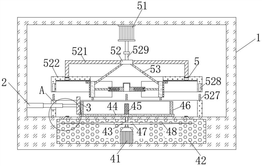
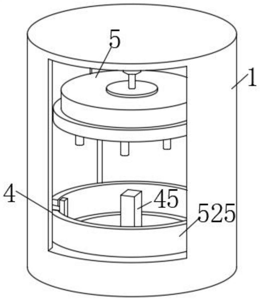
[0032] Such as Figure 1-7As shown, the high-precision bearing production and processing equipment of an industrial robot proposed by the present invention includes a base 1, an electric telescopic rod 2 and a cutting tool 3, and one side of the inner surface of the base 1 is provided with an electric telescopic rod 2, and the electric telescopic rod One end of 2 is provided with a cutting tool 3, the bottom end of the inner surface of the base 1 is provided with a rotating assembly 4, and the top of the inner surface of the base 1 is provided with a fixed assembly 5 at a position corresponding to the rotating part;

[0033] The rotating assembly 4 includes a motor 41, a movable chamber 42, a rotating rod 43, a rotating disk 44, a limit post 45 and a bearing ring 46. The bottom end of the inner surface of the base 1 is provided with a movable chamber 42, and the inside of the movable chamber 42 is provided with a motor 41 One end of the output shaft of the motor 41 is fixedly ...

Embodiment 2

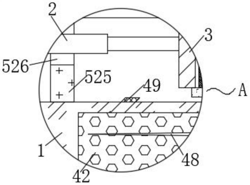
[0037] During the cutting process, the bearing ring 46 and the cutting tool 3 produce high-speed friction, so a large amount of heat will be generated, which will affect the loading and unloading of the bearing ring 46 by the operator. There is a connecting ring 47, and the outer surface of the connecting ring 47 is fixedly connected with several groups of fan blades 48 at equal annular distances. The bottom end of the inner surface of the base 1 is located around the turntable 44. There are several groups of air outlet nozzles 49, and the air outlet nozzles 49 The inside of the movable chamber 42 communicates with the inside of the movable chamber 42, and the two sides of the inner surface of the movable chamber 42 are hollowed out to facilitate the circulation of gas. , the connecting ring 47 drives the fan blade 48 on its surface to rotate, thereby pushing the airflow below the fan blade 48 to its upper side, and making it spray to the surroundings of the bearing ring 46 thr...

Embodiment 3

[0039] A certain amount of iron filings will be produced during the cutting process. Since the bearing is usually in a high-speed running state during the cutting process, the iron filings are easy to splash around, which is not only difficult to clean, but also easy to damage the surface of the equipment when the iron filings are splashed. cause damage, even accidental injury to the operator, and increase the danger in the processing process. The outer surface of the fixed block 52 is fixedly connected with the limit frame 521, and the first shield frame 522 is arranged below the limit frame 521. The first shield The outer surface of the upper end of the frame 522 is provided with an annular groove 523, and the interior of the annular groove 523 is provided with an annular plate 524. The limit frame 521 penetrates into the interior of the annular groove 523 and is fixedly connected with the annular plate 524. The limit frame 521 is connected to the first The shielding frame 52...


PUM


Abstract

The invention belongs to the technical field of machining, and particularly relates to high-precision bearing producing and machining equipment of an industrial robot, the high-precision bearing producing and machining equipment comprises a base, an electric telescopic rod and a cutting tool, the electric telescopic rod is arranged on one side of the inner surface of the base, the cutting tool is arranged at one end of the electric telescopic rod, and a rotating assembly is arranged at the bottom end of the inner surface of the base; through mutual cooperation of the rotating assembly and the fixing assembly, the output end of an air pump pushes a connecting rod and a fixing block downwards, and when a limiting groove and a limiting column are matched and abut against each other, an output shaft of the air pump continuously pushes the fixing block downwards, so that the two ends of a supporting plate rotate, and the bottom end of the supporting plate pushes a pushing block towards one side; the pushing block pulls the movable rod to move along the movable groove and stretches the spring till the spring is attached to the inner wall of the bearing ring, so that the bearing rings of different specifications can be clamped and fixed, and meanwhile the motor can be used for driving the limiting column to drive the whole rotating assembly to rotate along with the rotating disc.

Description

technical field [0001] The invention relates to the technical field of mechanical processing, in particular to high-precision bearing production and processing equipment for industrial robots. Background technique [0002] The bearing of an industrial robot is one of its key supporting parts. At present, the general process of bearing processing includes bearing steel raw materials, turning into inner sleeves, outer sleeves, bead blanks, heat treatment, and grinding into finished materials (the grinding process includes internal grinding , cylindrical grinding, centerless grinding), and finally assemble the finished product. [0003] The production and processing of bearings need to go through many processes, especially for the cutting process of its outer ring, the requirements are very strict. When the outer ring of the bearing needs to be cut, it is usually fixed by the fixture, and then the It cuts. [0004] The clamps in the prior art are usually clamped on both sides...

Claims


Application Information

Patent Timeline
Patent Type & Authority Applications(China)
IPC IPC(8): B23D79/00B23Q3/00B23Q11/00B23Q11/08
CPCB23D79/00B23Q3/00B23Q11/0032B23Q11/08
Inventor 赵金鹏朱勤孙友峰梅厉厂许永贵
Owner 安徽安步轴承有限公司
Why Eureka
Try Eureka