Supercharge Your Innovation With Domain-Expert AI Agents!

Drilling, milling, sawing and milling production line and door and window machining method

A production line and milling processing technology, which is applied in the field of door and window processing equipment, can solve the problems of low processing efficiency, long overall length of the production line, and unreasonable layout of the production line, etc., and achieve the goal of canceling the manual sorting process, shortening the length, and improving processing efficiency Effect

Active Publication Date: 2022-04-29
山东鑫迈德数控设备有限公司
View PDF7 Cites 0 Cited by
  • Summary
  • Abstract
  • Description
  • Claims
  • Application Information

AI Technical Summary

Problems solved by technology

[0003]At present, in order to improve the efficiency of door and window processing, the door and window processing equipment on the market gradually adopts the production method of milling first and then cutting, but the layout of the existing door and window production line is not Reasonably, it generally arranges all the processing centers on the same straight line, but this kind of production line layout will make the overall length of the production line very long, and will make the processing efficiency of the entire processing line relatively low, and this kind of production line layout will be Occupy a lot of factory space

Method used


Image

  • Drilling, milling, sawing and milling production line and door and window machining method
  • Drilling, milling, sawing and milling production line and door and window machining method
  • Drilling, milling, sawing and milling production line and door and window machining method

Examples


Embodiment Construction

[0028] The following will clearly and completely describe the technical solutions in the embodiments of the present invention with reference to the accompanying drawings in the embodiments of the present invention. Obviously, the described embodiments are only some, not all, embodiments of the present invention. Based on the embodiments of the present invention, all other embodiments obtained by persons of ordinary skill in the art without making creative efforts belong to the protection scope of the present invention.

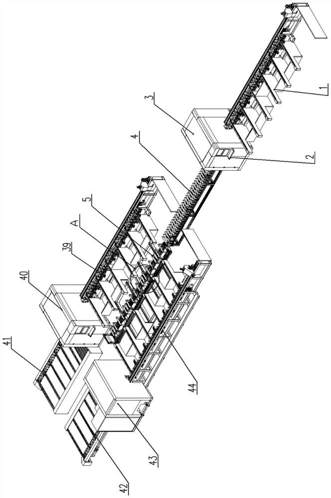
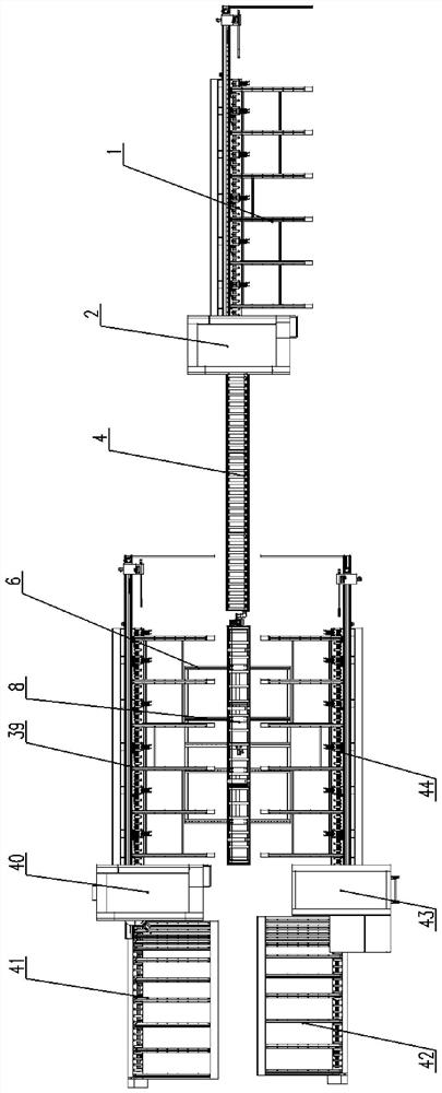
[0029] Such as figure 1 , 2 As shown, the present invention provides a drilling, milling, sawing and milling production line, which includes a drilling and milling machining center 2, the feeding end of the drilling and milling machining center 2 is provided with a drilling and milling feeding device 1, and the drilling and milling machining center The discharge end of 2 is provided with a drilling and milling blanking device 4 and a ferry car 5 in sequence a...


PUM


Abstract

The invention provides a drilling, milling, sawing and milling production line and a door and window machining method, and belongs to the field of door and window machining equipment.The drilling, milling, sawing and milling production line comprises a drilling and milling machining center, a drilling and milling feeding device is arranged at the feeding end of the drilling and milling machining center, and a drilling and milling discharging device and a ferry lathe bed are sequentially arranged at the discharging end of the drilling and milling machining center in the discharging direction; a saw cutting feeding device and a saw milling feeding device are arranged on the two sides of the ferry lathe bed respectively, and a saw cutting machining center and a saw cutting discharging device are sequentially arranged at the discharging end of the saw cutting feeding device. A sawing and milling machining center and a sawing and milling discharging device are sequentially arranged at the discharging end of the sawing and milling feeding device. A second sliding frame horizontally slides on the ferry bed body, the second sliding frame can move in the direction close to the feeding end of the sawing and cutting feeding device or the direction close to the feeding end of the sawing and milling feeding device, and the sliding direction of the second sliding frame is perpendicular to the material conveying direction of the drilling and milling discharging device. The sectional material machining device has the beneficial effects that the occupied area is reduced, and the sectional material machining efficiency is improved.

Description

technical field [0001] The invention relates to the technical field of door and window processing equipment, in particular to a drilling, milling, sawing, sawing and milling production line and a door and window processing method. Background technique [0002] Due to its low density, light weight, strong corrosion resistance, good weather resistance and good processing performance, aluminum profiles are becoming more and more popular. Aluminum alloy doors and windows often involve various The milling of holes and slots of different types is generally done by copying milling machines or CNC machining centers to complete the processing of aluminum alloy door and window holes and slots. [0003] At present, among the door and window processing equipment on the market, in order to improve the processing efficiency of doors and windows, it gradually adopts the production method of milling first and then cutting, but the layout of the existing door and window production line is un...

Claims


Application Information

Patent Timeline
IPC IPC(8): B23P23/06
CPCB23P23/06
Inventor 朱庆亮骆伟
Owner 山东鑫迈德数控设备有限公司
Features
  • R&D
  • Intellectual Property
  • Life Sciences
  • Materials
  • Tech Scout
  • Unparalleled Data Quality
  • Higher Quality Content
  • 60% Fewer Hallucinations
Learn More