Automatic edge sealing device for plywood production

An edge banding device and plywood technology, which is applied to other plywood/plywood appliances, conveyor control devices, household components, etc., can solve problems such as waste of space resources, easy deformation of plates, and inability to use all support and guide rollers. The effect of ensuring uniformity and preventing sheet deformation

Pending Publication Date: 2022-04-29
TAOJIANG HONGSEN WOOD IND
View PDF19 Cites 0 Cited by
  • Summary
  • Abstract
  • Description
  • Claims
  • Application Information

AI Technical Summary

Problems solved by technology

[0004] However, due to the different sizes of the boards, it is difficult to support the entire span of the boards with two sets of opposing rollers, and there is a certain suspended distance in the boards, which makes the boards easily deformed by gravity
[0005] In order to solve this problem, for example, the HC-160 high-speed edge banding machine produced by Xin Future Woodworking Machinery Co., Ltd. has added support guide rollers to prevent the board from hanging in the air, but the axial span of the support guide rollers is a certain distance. For For small-span panels, the supporting and guiding rollers cannot be fully used, occupying space and wasting resources

Method used


Image

  • Automatic edge sealing device for plywood production
  • Automatic edge sealing device for plywood production
  • Automatic edge sealing device for plywood production

Examples


Embodiment 1

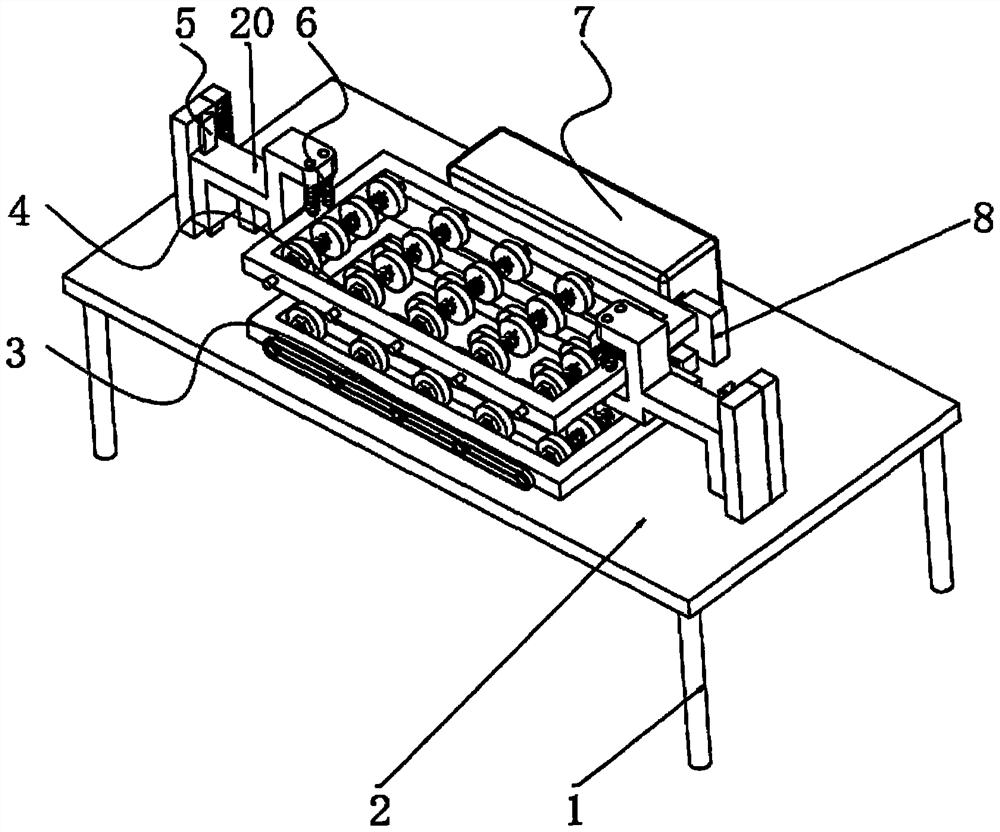
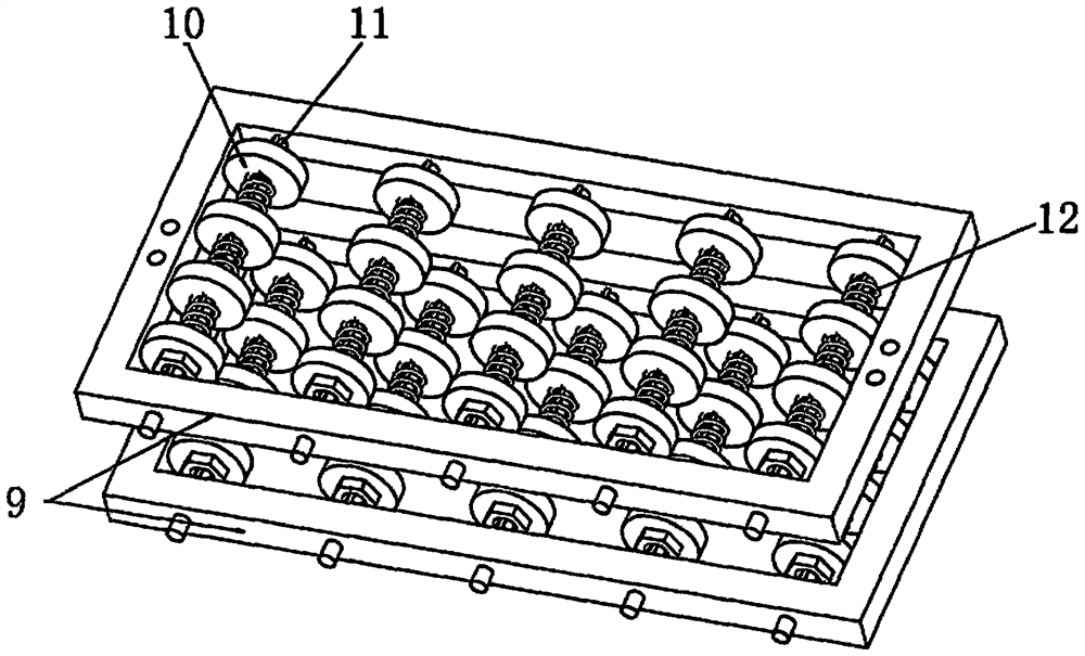
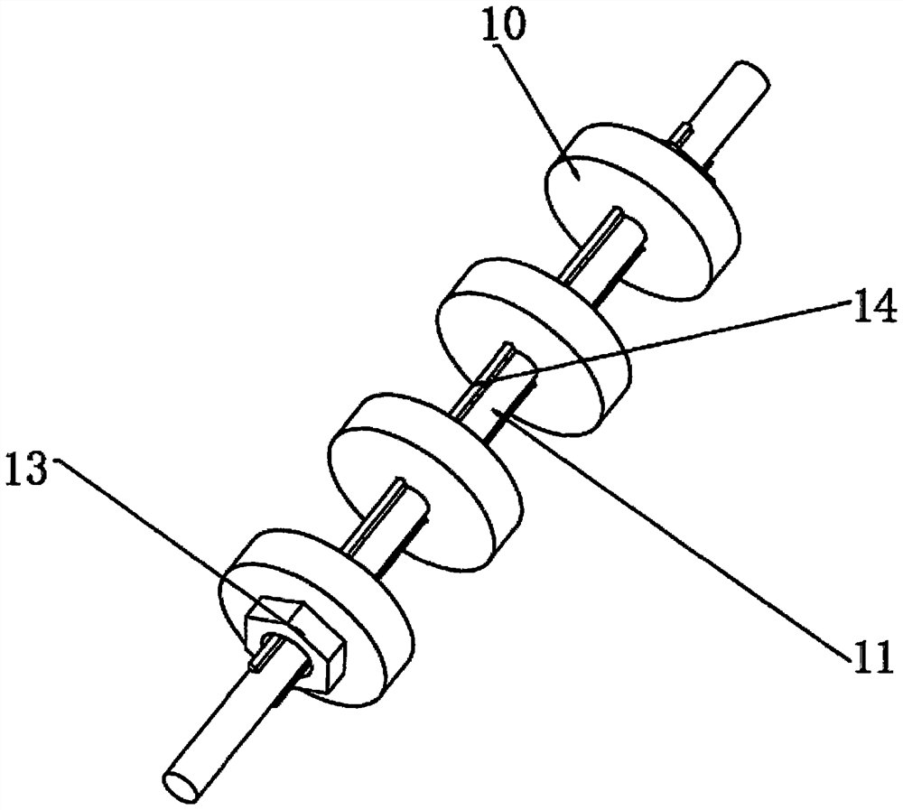
[0037] An automatic edge banding device for plywood production, such as Figure 1-3As shown, it includes a base 2 that is supported and fixed on the ground by legs 1. The top outer wall of the base 2 is provided with an active conveying assembly 3. The outer wall of the base 2 is connected with a bracket 20 through two sets of drive lifting components 5. The bracket 20 is connected by The member 6 is connected with the same group of passive pressing components 4. The active conveying component 3 has the same structure as the passive pressing component 4, and specifically includes a rectangular frame 9 and multiple sets of rollers 10. The inner wall of the rectangular frame 9 is rotatably connected to multiple set transmission shaft 11, the outer wall of the transmission shaft 11 is welded with a transmission protrusion 14, the inner wall of the roller 10 is provided with a groove matching the transmission protrusion 14, and the groove and the transmission protrusion 14 are in c...

Embodiment 2

[0044] An automatic edge banding device for plywood production, such as figure 1 As shown, in order to solve the problem of precise control of position; this embodiment makes the following improvements to the driving lifting assembly 5 in Embodiment 1: the driving lifting assembly 5 includes a rack 23, a gear 24 and a "U" frame 27, the The top outer wall of the base 2 is fixed with a support plate 22 by bolts, and the support plate 22 is slidably connected with the bracket 20 through a linear slide rail 21. On the outer wall of the bracket 20, one side outer wall of the gear 24 meshes with the outer wall of the rack 23, and the other side outer wall of the gear 24 meshes with the "U" frame 27 through the teeth 26 arranged on the side wall of the gear 24, The inner wall of the "U" frame 27 is slidably connected with a guide slide bar two 28, and the guide slide bar two 28 is fixed on the bottom outer wall of the base 2 by bolts, and the bottom outer wall of the base 2 is fixed ...


PUM


Abstract

The invention discloses an automatic edge sealing device for plywood production, and relates to the technical field of edge sealing machines. The device specifically comprises a base supported and fixed to the ground through supporting legs, an active conveying assembly is arranged on the outer wall of the top of the base, and the outer wall of the base is connected with a support through two driving lifting assemblies. The driving conveying assembly and the driven pressing assembly are matched to convey plates, the rollers are matched with the transmission protrusions through grooves to achieve transmission connection between the rollers and the transmission shaft, the rollers and the transmission protrusions which are in clearance fit can axially slide, and when a limiting adjusting nut rotates, the rollers can be driven to rotate, so that the plates can be conveyed. The roller wheels on the outermost side are extruded through the action of the threads to slide, so that the total span of the roller wheels in the same group is changed, the supporting span can be adjusted in a targeted mode according to the actual plate size, the roller wheels in the device participate in supporting work no matter what size plate is, and multi-point supporting and full resource utilization are achieved.

Description

technical field [0001] The invention relates to the technical field of edge banding machines, in particular to an automatic edge banding device for plywood production. Background technique [0002] Plywood is to use adhesives to laminate and bond multiple layers of thin boards to form a stronger board. It is mostly used for building decoration. For the aesthetics of the decoration, the sides of the plywood need to be edge-sealed. [0003] In the prior art, the edge banding machine generally has a plate conveying device, and the conveying device is realized by two sets of opposite conveying rollers, such as the fully automatic small household sealing and repairing machine produced by Qingdao Massent Machinery Technology Co., Ltd. Two sets of opposite conveying rollers are used to convey the plate, and cooperate with the edge-sealing mechanism to carry out edge-sealing. [0004] However, due to the different sizes of the plates, it is difficult to support the entire span of t...

Claims


Application Information

Patent Timeline
IPC IPC(8): B65G13/07B65G39/02B65G43/00B27N7/00B27D5/00
CPCB65G13/07B65G39/02B65G43/00B27N7/00B27D5/003B65G2201/022
Inventor 李泽云张伟华李杰
Owner TAOJIANG HONGSEN WOOD IND
Why Eureka
Try Eureka