Liquid crystal display device and driving method thereof

A liquid crystal display device and liquid crystal technology, applied in static indicators, nonlinear optics, instruments, etc., can solve problems such as difficulty in writing image signals, reduced writing time, insufficient processing capacity of excitation components or insufficient current drive capacity, etc.

Inactive Publication Date: 2004-03-31
ALPS ALPINE CO LTD
View PDF0 Cites 2 Cited by
  • Summary
  • Abstract
  • Description
  • Claims
  • Application Information

AI Technical Summary

Problems solved by technology

[0009] Moreover, since the writing time of each pixel is reduced as the number of pixels of the entire display device is increased, and the parasitic capacity of each source wiring is weakened, it is difficult to write an image signal. accomplish
Therefore, there is a problem of insufficient processing capability or current driving capability of the excitation part, and there is also a problem that a high-performance and expensive excitation part needs to be used in this case.

Method used


Image

  • Liquid crystal display device and driving method thereof
  • Liquid crystal display device and driving method thereof
  • Liquid crystal display device and driving method thereof

Examples


Embodiment Construction

[0025] Refer below figure 1 and figure 2 , an embodiment of the present invention will be described.

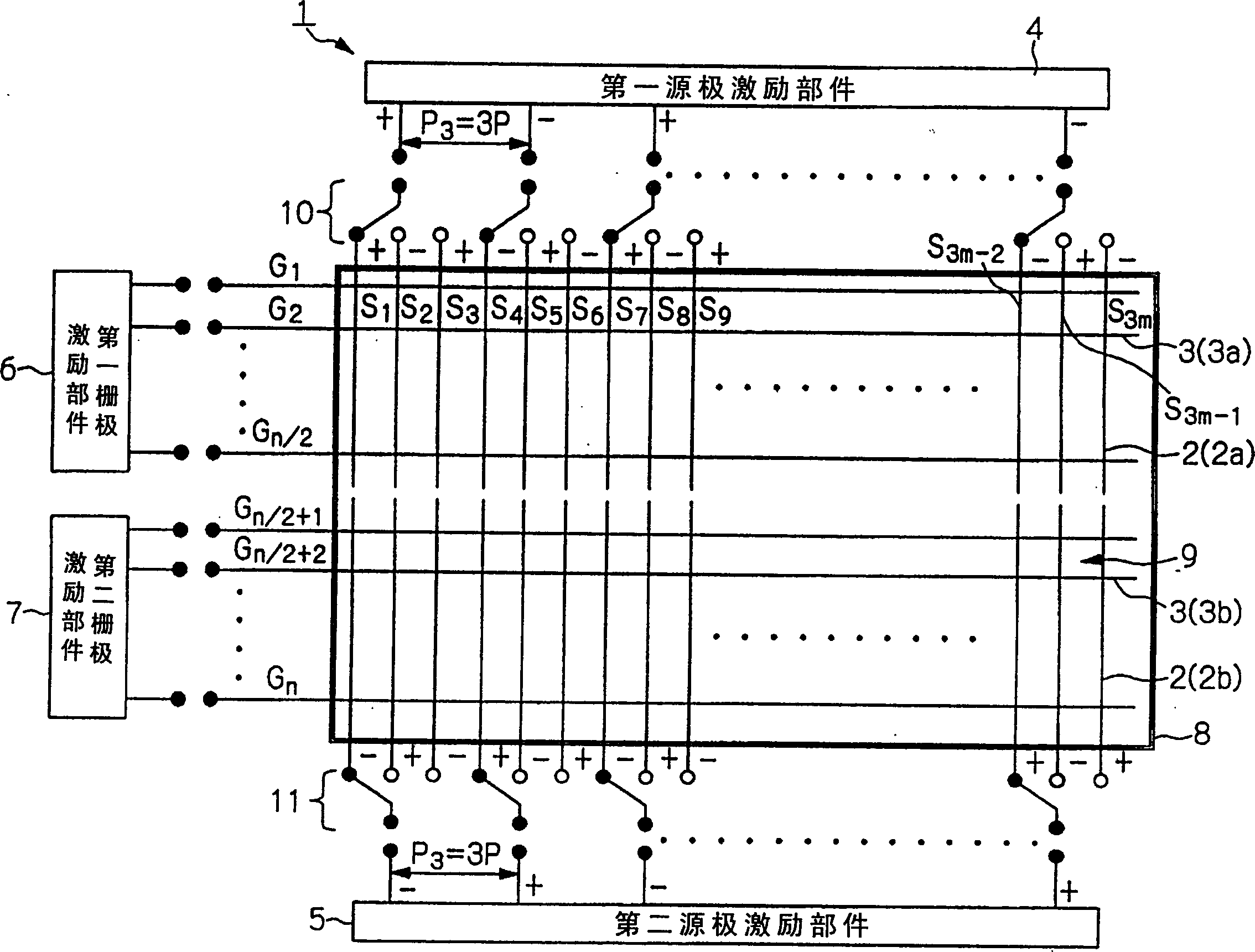
[0026] figure 1 In order to represent a schematic structure diagram for a kind of thin film transistor (TFT) active matrix liquid crystal display device of the present embodiment, what 2 (2a, 2b) represents is the source line, and what 3 (3a, 3b) represents 4 denotes the first source drive component, 5 denotes the second source drive component, 6 denotes the first gate drive component, and 7 denotes the second gate drive component.

[0027] The liquid crystal display device 1 as the present embodiment is as figure 1 As shown, several source lines 2 (S 1 , S 2 ,...,S 3m-1 , S 3m ) and several gate lines 3 (G 1 ,...,G n ), the regions divided by these source lines 2 and gate lines 3 constitute individual pixels. Inside each pixel, a thin film transistor (TFT) and a pixel electrode not shown in the figure are also provided.

[0028] Several source lines 2 are divi...


PUM


Abstract

A liquid crystal display having a plurality of source lines in the display area which are each divided into two groups includes a first source driver for applying image signals to a first group of the divided source lines, a second source driver for applying image signals to a second group, a first gate driver operative to apply scanning signals to one segment of a plurality of gate lines that extends across the first group of the divided source lines, and a second gate driver for applying scanning signals to the other segment of a plurality of gate lines that extends across the second group of the divided source lines, and switching assemble.

Description

technical field [0001] The invention relates to a liquid crystal display device and a corresponding driving method, in particular to an active matrix driven liquid crystal display device suitable for high-definition display. Background technique [0002] In the field of liquid crystal display (Liquid Crystal Display, hereinafter abbreviated as LCD) technology that can be applied to various electronic devices, in recent years efforts have been made to improve image quality so as to realize high-definition display. For a liquid crystal display device (LCD) that uses a thin film transistor (Thin Film Transistor, hereinafter abbreviated as TFT) at each pixel switching element and operates according to a thin film transistor (TFT) type active matrix drive method, in order to achieve high-definition Display needs to reduce the pixel pitch and increase the number of pixels accordingly. It has been proposed that several signal lines (source lines) and several integrated circuit (IC)...

Claims


Application Information

Patent Timeline
Patent Type & Authority Patents(China)
IPC IPC(8): G02F1/133G09G3/20G09G3/36
CPCG09G3/3666G09G2310/0297G02F1/133
Inventor 蛇口广行
Owner ALPS ALPINE CO LTD
Why Eureka
Try Eureka