Condenser heat transfer tube submerged jet cleaning process test bench and test method thereof

A process test and heat transfer tube technology, applied in the field of condenser heat transfer tube submerged jet cleaning process test bench, can solve the problems of reducing steam turbine efficiency, increasing coal consumption for power generation, reducing cooling water volume, etc., to achieve optimal cleaning effect, The effect of easy cleaning effect

Pending Publication Date: 2022-04-29
苏州天河中电电力工程技术有限公司
View PDF0 Cites 0 Cited by
  • Summary
  • Abstract
  • Description
  • Claims
  • Application Information

AI Technical Summary

Problems solved by technology

[0003] However, due to the attachment of microorganisms and unclean substances in the circulating water to the inner wall of the condenser heat exchange tube (copper tube, titanium tube or stainless steel tube), the thermal resistance will increase; due to the dirt and scaling on the inner wall of the heat exchange tube, the heat transfer If the coefficient is reduced, the heat exchange tube will be blocked if it is not treated for a long time, the cooling water flow area through the heat exchange tube will be reduced, the water flow resistance will increase, and the cooling water volume will decrease. Under a certain steam load, the temperature rise of the cooling water will exceed normal These will cause the vacuum of the condenser to drop, reduce the efficiency of the steam turbine, increase the coal consumption of power generation, and serious fouling will also affect the output of the steam turbine
[0004] Water jet flushing is the most common in the current online cleaning device for condenser heat transfer tubes. The structure of the cleaning device is complex, the manufacturing cost is high, and the cycle is long. Before producing the online cleaning device for condenser heat transfer tubes, the cleaning process must be verified. Effect

Method used


Image

  • Condenser heat transfer tube submerged jet cleaning process test bench and test method thereof
  • Condenser heat transfer tube submerged jet cleaning process test bench and test method thereof

Examples


Embodiment

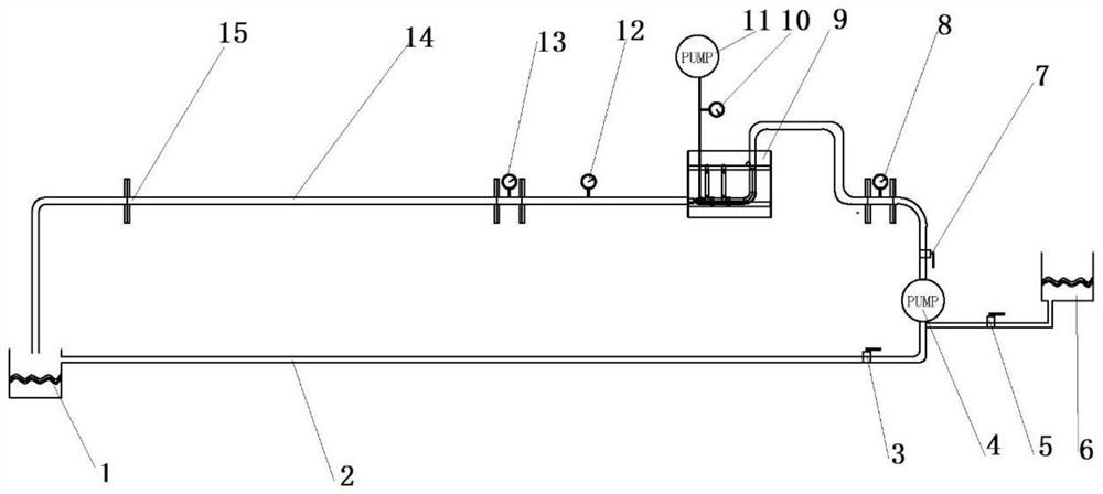
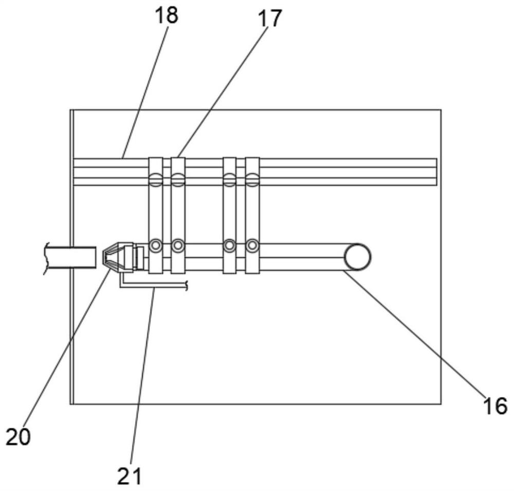
[0042] Example: see attached figure 1 and 2 , the present invention provides a technical solution: a test bench for the submerged jet cleaning process of the condenser heat transfer tube, which includes:

[0043] The simulated water chamber 9 is fixed with a fixed rod 18 inside the simulated water chamber 9;

[0044] The nozzle 20, the nozzle 20 is fixedly connected to the fixed rod 18 by a plurality of fixed connecting rods 17, the fixed rod 18 is fixedly connected to the nozzle 20 by a plurality of fixed connecting rods 17, and the inner cavity of the nozzle 20 is sealed and communicated with one end of the compressed gas circuit pipe 21 , the liquid inlet end of the nozzle 20 is connected to one end of the high-pressure water circuit pipe 16; specifically, the simulated water chamber 9 can simulate the pressure environment of the water chamber, and the nozzle 20 is fixedly installed, and the spraying state of the nozzle 20 is observed during the flushing process , and tes...


PUM


Abstract

The invention discloses a steam condenser heat transfer tube submerged jet cleaning process test bench and a test method thereof, and the test bench comprises a simulation water chamber which is internally and fixedly provided with a fixed rod; the spray head is fixedly connected to the fixed rod through a plurality of fixed connecting rods, an inner cavity of the spray head communicates with one end of a compressed gas loop pipe in a sealed mode, and the liquid inlet end of the spray head communicates with one end of a high-pressure water loop pipe; one end of the heat transfer simulation pipe is connected into the simulation water chamber, and the other end of the heat transfer simulation pipe is connected with a collection water tank; and a gas outlet end of the gas supply system is fixedly communicated with the other end of the compressed gas loop pipe. According to the device and the method, the internal environment of the condenser water chamber and the heat transfer pipe can be completely simulated, the cleaning effect of the cleaning mechanism is convenient to observe, the cleaning process is convenient to adjust, and the cleaning effect of the cleaning mechanism is optimized.

Description

technical field [0001] The invention specifically relates to the technical field of a cleaning device for a heat transfer tube of a condenser, in particular to a test bench for a submerged jet cleaning process of a heat transfer tube of a condenser and a test method thereof. Background technique [0002] The condensing equipment plays the role of cold source in the thermodynamic cycle of the steam turbine device. Reducing the exhaust steam pressure and exhaust temperature of the steam turbine can improve the thermal efficiency of the cycle. With the continuous improvement of the unit parameters and capacity, the water vapor quality in the thermal system is raised higher requirements. [0003] However, due to the attachment of microorganisms and unclean substances in the circulating water to the inner wall of the condenser heat exchange tube (copper tube, titanium tube or stainless steel tube), the thermal resistance will increase; due to the dirt and scaling on the inner wal...

Claims


Application Information

Patent Timeline
Patent Type & Authority Applications(China)
IPC IPC(8): G01M10/00
CPCG01M10/00
Inventor 王金龙汪明辉肖晓南杨杰刘顺林世昌罗杰刘颖李天昊徐华悦
Owner 苏州天河中电电力工程技术有限公司
Why Eureka
Try Eureka