Optical module capable of being quickly aligned and assembled

An optical module and fast technology, applied in the field of optical modules, can solve the problems of increasing optical energy loss in the transmission process, high technical difficulty, and low processing efficiency, so as to omit the packaging glue and packaging process, simplify the fixed alignment relationship, and improve the docking The effect of precision

Active Publication Date: 2022-04-29
SHENZHEN AFALIGHT CO LTD
View PDF9 Cites 0 Cited by
  • Summary
  • Abstract
  • Description
  • Claims
  • Application Information

AI Technical Summary

Problems solved by technology

[0004] The above-mentioned optical module mainly has the following shortcomings in practice. First, it adopts the design of the optical converter 4 to change the transmission direction of the optical path, which not only has a complex structure and low processing efficiency, but also increases the loss of optical energy during transmission. Second, , the matching precision required between the various components is high, the production technology is difficult and the cost is high. Third, due to the optical path design of the optical lens and optical mirror, the coupling process is complicated, resulting in low coupling accuracy and efficiency of the overall product

Method used


Image

  • Optical module capable of being quickly aligned and assembled
  • Optical module capable of being quickly aligned and assembled
  • Optical module capable of being quickly aligned and assembled

Examples


example 1

[0064] Example 1: L=150μm, D1 / D2=0.8 (D2 / D1=1 / 0.8), D2=750μm, the total length of the plastic optical fiber 30 is less than 0.016 meters, (2mm / 150μm)*(1 / 0.8)*10 -750μm / 250μm m = 0.016 m.

example 2

[0065]Example 2: When L=50 μm, D1 / D2=0.9 (D2 / D1=1 / 0.9), D2=500 μm, the total length of the plastic optical fiber 30 is less than 0.44 meters, (2mm / 50 μm) *(1 / 0.9)*10 -500μm / 250μm m = 0.44 m.

example 3

[0066] Example 3: (the most typical application parameters) when L=100μm, D1 / D2=0.95 (D2 / D1=1 / 0.95), D2=250μm, the total length of the plastic optical fiber 30 is less than 2.11 meters, (2mm / 100μm) * (1 / 0.95)*10 -250μm / 250μm m = 2.11 m.
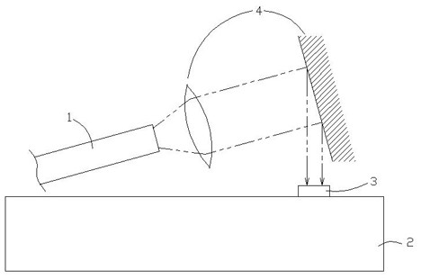
[0067] The design idea of ​​the plastic optical fiber 30 in the present invention is as follows: First, the functional optical modules 21 on the control circuit board 20 are all placed horizontally, and the glass optical fiber (GOF) 1 will break when bent, so in order to realize the transmission of optical signals, Then it is necessary to increase the optical converter 4, and the addition of the optical converter 4 will inevitably increase the cost of the product, and will also greatly increase the volume of the product. The biggest advantage of using glass optical fiber (GOF) 1 for optical transmission lies in long-distance optical transmission. The signal attenuation is weak, but in practical applications, most signal transmissions are com...


PUM

PropertyMeasurementUnit
pore sizeaaaaaaaaaa
lengthaaaaaaaaaa

Abstract

The invention relates to an optical module capable of being quickly aligned and assembled, which comprises an optical module and an optical fiber connector, and is characterized in that the optical module comprises a connector, a control circuit board and a plastic optical fiber, the control circuit board is connected to the connector, a functional optical module is arranged on the control circuit board, and the plastic optical fiber is provided with an optical fiber end surface; the optical fiber end face corresponds to the functional optical module, the optical fiber connector is connected between the plastic optical fiber and the control circuit board, and the optical fiber connector is used for fixing the plastic optical fiber on the control circuit board, so that the optical fiber end face of the plastic optical fiber corresponds to the functional optical module on the control circuit board.

Description

technical field [0001] The invention relates to an optical module, in particular to an optical module in which an optical fiber and a functional module can be quickly aligned and assembled. Background technique [0002] The optical module is called the optical transceiver integrated module. It is the core device in optical communication. It can complete the process of converting optical signals into electrical signals and converting electrical signals into optical signals. It is mainly composed of optoelectronic devices, functional circuits and optical interfaces. The optoelectronic device includes two parts: receiving and emitting. In simple terms, its receiving part is responsible for converting optical signals into electrical signals, and its transmitting part converts electrical signals into optical signals. [0003] like figure 1 As shown, the glass optical fiber (GOF) 1 in the traditional optical module is arranged obliquely, and the functional module 3 is arranged o...

Claims


Application Information

Patent Timeline
Patent Type & Authority Applications(China)
IPC IPC(8): G02B6/42
CPCG02B6/4219
Inventor 黄君彬付全飞童小琴
Owner SHENZHEN AFALIGHT CO LTD
Why Eureka
Try Eureka