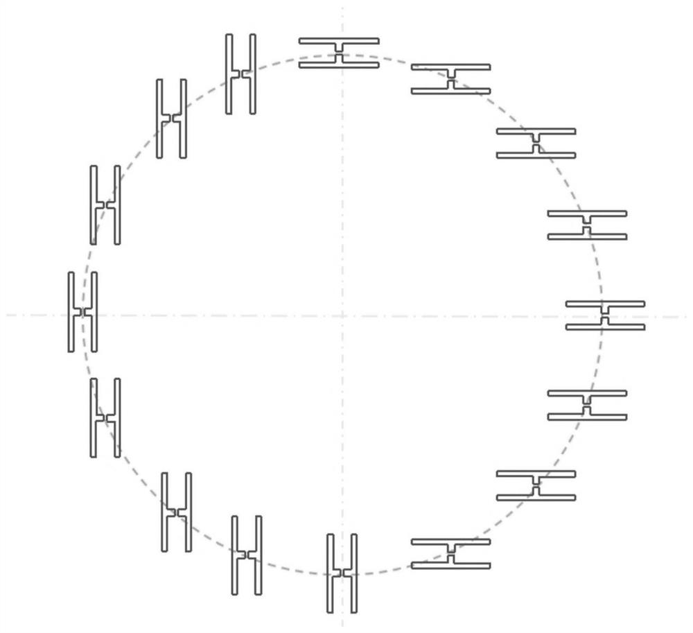
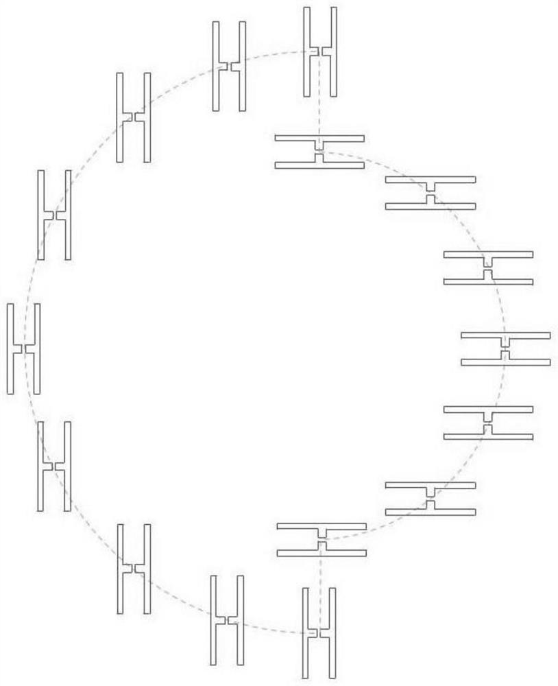
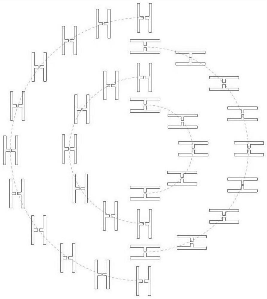
Circular track photoconductive antenna array for terahertz polarization imaging system
A photoconductive antenna and antenna array technology, applied in the field of imaging, can solve the problems of fixed and single electrode unit direction, and inability to obtain the polarization information data of the object to be measured, so as to reduce the number of samples, improve the imaging speed, and fast terahertz polarization imaging Effect
- Summary
- Abstract
- Description
- Claims
- Application Information
AI Technical Summary
Problems solved by technology
Method used
Image

Examples
Embodiment Construction
[0021] In order to make the object, technical solution and advantages of the present invention clearer, the present invention will be described in detail below with reference to the accompanying drawings and specific embodiments.
[0022] In order to make the object, technical solution and advantages of the present invention clearer, the present invention will be further described in detail below in conjunction with the accompanying drawings and embodiments. It should be understood that the specific embodiments described here are only used to explain the present invention, not to limit the present invention.
[0023] The polarization imaging part, that is, the photoconductive antenna array with a special structure circular track, is combined with the terahertz time-domain spectroscopy system to form a terahertz polarization imaging system. The pulse generated by the femtosecond laser is divided into two paths after passing through the beam splitter, one path is the pump light,...
PUM
 Abstract
Description
Claims
Application Information
 - R&D
- Intellectual Property
- Life Sciences
- Materials
- Tech Scout
- Unparalleled Data Quality
- Higher Quality Content
- 60% Fewer Hallucinations
Browse by: Latest US Patents, China's latest patents, Technical Efficacy Thesaurus, Application Domain, Technology Topic, Popular Technical Reports.
© 2025 PatSnap. All rights reserved.Legal|Privacy policy|Modern Slavery Act Transparency Statement|Sitemap|About US| Contact US: help@patsnap.com