Electromagnetic power generation device for intelligent tire

A power generation device, electromagnetic technology, applied in the direction of electromechanical devices, tire measurement, tire parts, etc., can solve the problems of large output impedance, limited service life, large internal volume of tires, etc., to achieve high output power, strong stability, compact effect

Pending Publication Date: 2022-04-29
NANJING UNIV OF SCI & TECH
View PDF0 Cites 0 Cited by
  • Summary
  • Abstract
  • Description
  • Claims
  • Application Information

AI Technical Summary

Problems solved by technology

The electrostatic power supply device requires an initial polarization voltage or charge, and at the same time, its output impedance is large, which is not suitable for energy supply; the piezoelectric power supply device has a limited number of deformations due to the piezoelectric material, which greatly limits its use. Lifespan; although the mechanical power supply device generates a large amount of energy, due to the large size of each component, it occupies a large volume inside the tire, which has a certain impact on the internal pressure of the wheel.
[0004] The existing electromagnetic smart tire power generation device mainly outputs energy through the change of the magnetic flux in the coil caused by the reciprocating motion of a single permanent magnet inside the coil. This type of power supply device cannot make full use of the magnetic force of the permanent magnet, and the energy density is low. Strenuous exercise can adversely affect its magnetism and the stability of the device

Method used


Image

  • Electromagnetic power generation device for intelligent tire
  • Electromagnetic power generation device for intelligent tire
  • Electromagnetic power generation device for intelligent tire

Examples


Embodiment 1

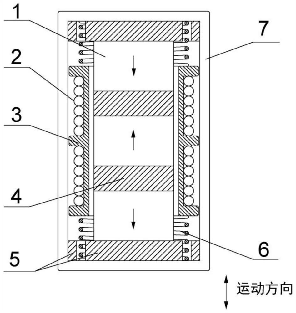
[0026] Take N=3, that is, the combination of 3 cylindrical permanent magnets (N35) and 2 inner yokes (steel008) to generate a magnetic field, the height of the cylindrical permanent magnet 1 is H1, the cylindrical permanent magnet 1 and the inner yoke The radii of 4 are all R, and the heights of the inner yokes 4 are all H4, H1=5mm, R=4mm, H4=2.5mm. Such as Figure 4 , Figure 5 As shown, the internal magnetic field density diagram of the power generation device and the magnetic induction intensity diagram along the coil distribution direction at a distance of 6.5 mm from the axis of the cylindrical permanent magnet can be obtained through simulation, which is obtained by Figure 5 It is not difficult to see that the maximum magnetic induction in this direction can reach about 0.7T, and there is an average magnetic induction of about 0.4T, that is, when H4 satisfies H4=0.25R+0.3H1, a stronger magnetic induction can be obtained under the condition of limiting the volume of the...


PUM


Abstract

The invention provides an electromagnetic power generation device for an intelligent tire, which comprises N cylindrical permanent magnets, N-1 groups of coil windings, a coil framework, N-1 inner magnet yokes, two rubber buffers, two springs and an outer magnet yoke, and N is equal to 2-7. The N cylindrical permanent magnets and the N-1 inner magnet yokes are arranged in a staggered mode along the inner wall of the coil framework from top to bottom, and the magnetizing directions of the adjacent cylindrical permanent magnets are opposite. The coil framework is a cylinder, N-1 winding grooves are distributed in the circumferential outer wall of the coil framework at equal intervals in the axial direction, and a coil winding is arranged in each winding groove. The outer magnet yoke is a cylindrical shell, the two rubber buffers are fixed to the inner wall of the top face and the inner wall of the bottom face of the outer magnet yoke respectively, and the springs are embedded in the rubber buffers and connected with the framework. Due to deformation in the wheel movement process, the coil reciprocates to generate volt-level voltage and milliwatt-level energy, and after output energy is subjected to rectification filtering and other processing, passive power supply to the TPMS can be achieved.

Description

technical field [0001] The invention belongs to the field of automobile safety, and in particular relates to an electromagnetic power generation device used for smart tires. Background technique [0002] Tires are the only contact point between the car and the road, and have a lot to do with the safety of the car on the road. In recent years, with the improvement of national road traffic conditions, the driving speed of automobiles has been greatly improved, and once a tire blows out of a high-speed automobile, serious traffic accidents may occur and casualties may occur. According to statistics, 46% of traffic accidents on highways are caused by tire failures, among which punctures account for 70% of the total tire accidents. At the same time, after entering the winter, tires slipping on the road is also a major cause of tire accidents. Therefore, the research and development of intelligent tire technology is particularly important. [0003] The "smart" in smart tires re...

Claims


Application Information

Patent Timeline
Patent Type & Authority Applications(China)
IPC IPC(8): H02K35/04B60C23/04
CPCH02K35/04B60C23/041
Inventor 章逸飞吴凡刘梁徐照平
Owner NANJING UNIV OF SCI & TECH
Why Eureka
Try Eureka