Method for changing composition of catalytic cracking product

A catalytic cracking and product technology, applied in the direction of catalytic cracking, cracking, hydrocarbon oil treatment, etc., can solve the problems of small economic burden, high treatment cost, hazardous waste, etc., and achieve the transition period of increasing the yield of low-carbon olefins and adjusting product structure Short, beneficial to the effect of productive chemical materials

Pending Publication Date: 2022-05-03
CHINA PETROLEUM & CHEM CORP +1
View PDF6 Cites 0 Cited by
  • Summary
  • Abstract
  • Description
  • Claims
  • Application Information

AI Technical Summary

Problems solved by technology

[0002] In August 2016, FCC waste catalyst was listed in the "National Hazardous Waste List". According to the national hazardous waste management requirements, the production, storage, transportation, and disposal of FCC waste catalyst will be regulated by the state, and the treatment cost will increase significantly.
This method will generate a large amount of hazardous waste, which is a burden on the environment, and the disposal of hazardous waste is also a considerable economic burden for the refinery.

Method used


Image

  • Method for changing composition of catalytic cracking product
  • Method for changing composition of catalytic cracking product
  • Method for changing composition of catalytic cracking product

Examples


Embodiment 1

[0058] This example is used to illustrate a catalytic cracking method for adjusting product structure.

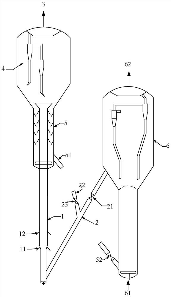
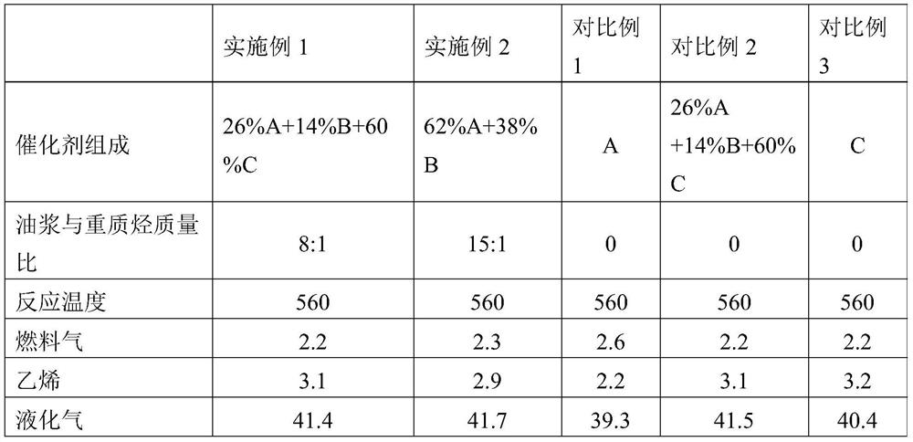
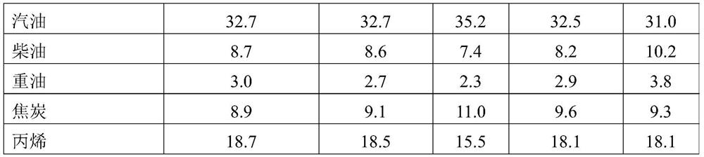
[0059] The experiment was carried out in a medium-sized device with continuous reaction-regeneration operation. The reactor was a riser reactor with an inner diameter of 16 mm and a height of 6 meters. The catalyst with a temperature of about 700°C is introduced into the bottom of the riser reactor through the regeneration inclined tube, wherein the composition of the catalyst is 26%A+14%B+60%C. The oil slurry is mixed with atomized water and sprayed into the riser reactor. The heavy raw oil is sprayed into the riser reactor 1 meter above the slurry nozzle, and the catalytic cracking reaction is carried out in the riser. After the reaction, the oil gas and the raw catalyst Entering the settler, the reaction oil gas and catalyst are quickly separated in the settler. The reaction oil and gas are further separated into gaseous products and liquid products. The raw catalyst s...

Embodiment 2

[0061] This example is used to illustrate: under the same reaction conditions as in Example 1, without adding the special catalyst C for the production of olefins, the effect of catalytic cracking product structure.

[0062] The reaction apparatus that adopts is with embodiment 1. Used reaction raw material, catalyst and main experiment procedure are the same as embodiment 1, difference is, the catalyst used in reaction system is composed of 62%A+38%B, and the weight ratio of the oil slurry injected simultaneously and heavy stock oil is different . The main operating conditions and results are listed in Table 3.


PUM


Abstract

The invention relates to a method for changing composition of a catalytic cracking product, and the method comprises the following steps: S1, selecting a running catalytic cracking system for producing gasoline and diesel oil, the system comprises a catalytic cracking reactor and a regenerator, and a catalytic cracking catalyst for producing gasoline and diesel oil circulates in the catalytic cracking reactor and the regenerator; s2, a transition catalyst is injected into the catalytic cracking system, continuous operation of catalytic cracking is kept, and a molecular sieve in the transition catalyst is composed of ZSM-5 molecular sieves; and S3, when the amount of the transition catalyst in the catalytic cracking system accounts for 30-40 wt% of the total storage amount of the catalyst in the system, injecting the catalytic cracking catalyst for producing low-carbon olefin into the system, and keeping continuous operation of catalytic cracking. According to the method, the problem that the yield of dry gas and coke is obviously increased in the rapid replacement process of the catalyst can be solved, and the yield of low-carbon olefin can be obviously increased.

Description

technical field [0001] The present application relates to petroleum refining and petrochemical processing, in particular to a method for changing the composition of catalytic cracking products. Background technique [0002] In August 2016, FCC waste catalyst was listed in the "National Hazardous Waste List". According to the national hazardous waste management requirements, the production, storage, transportation, and disposal of FCC waste catalyst will be regulated by the state, and the treatment cost will increase significantly. The spent catalyst of FCC is actually the unloading balancer of the catalytic cracking unit, which is not suitable for the production needs of its own unit. [0003] As the domestic refined oil market becomes saturated, many refineries will adjust their product structure, shifting from fuel-based to chemical-based. Among them, the composition of the catalyst for the catalytic cracking unit to produce gasoline and diesel as the target product is ve...

Claims


Application Information

Patent Timeline
IPC IPC(8): C10G11/05
CPCC10G11/05C10G2300/4006C10G2300/70Y02P20/52
Inventor 杨超谢朝钢朱根权袁起民马文明成晓洁
Owner CHINA PETROLEUM & CHEM CORP
Why Eureka
Try Eureka