A magnetic repulsion suspension pantograph

A pantograph and bow head technology, applied in the field of magnetic repulsion type suspension pantograph, can solve the problem of difficulty in adjusting the bow head, achieve stable and smooth ascending and descending, reduce wind resistance, and improve safety and service life. Effect

Active Publication Date: 2022-06-17
SOUTHWEST JIAOTONG UNIV
View PDF19 Cites 0 Cited by
  • Summary
  • Abstract
  • Description
  • Claims
  • Application Information

AI Technical Summary

Problems solved by technology

When the bow is raised, the electromagnetic valve for raising the bow is energized, and the air bag expands and deforms to drive the arm rod to move; when the bow is lowered, the solenoid valve is de-energized, the compressed air pressure in the air bag decreases, and the pantograph falls by its own gravity; During bow operation, it is difficult to actively and real-time control the small-scale height adjustment of the bow head. When the contact pressure between the pantograph slide plate and the catenary is inappropriate, off-line or too large, it is difficult to actively adjust the bow head Lifting to achieve a stable and continuous ideal contact pressure and continuous good pantograph-network relationship

Method used


Image

  • A magnetic repulsion suspension pantograph
  • A magnetic repulsion suspension pantograph
  • A magnetic repulsion suspension pantograph

Examples


Embodiment Construction

[0018] In order to make the purposes, technical solutions and advantages of the embodiments of the present invention clearer, the technical solutions in the embodiments of the present invention will be clearly and completely described below with reference to the accompanying drawings in the embodiments of the present invention. Obviously, the described embodiments These are some embodiments of the present invention, but not all of them. The components of the embodiments of the invention generally described and illustrated in the drawings herein may be arranged and designed in a variety of different configurations.

[0019] Accordingly, the following detailed description of the embodiments of the invention provided in the accompanying drawings is not intended to limit the scope of the invention as claimed, but is merely representative of selected embodiments of the invention. Based on the embodiments of the present invention, all other embodiments obtained by those of ordinary ...


PUM


Abstract

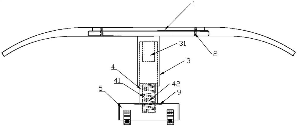
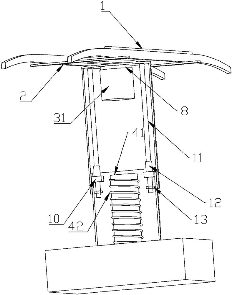
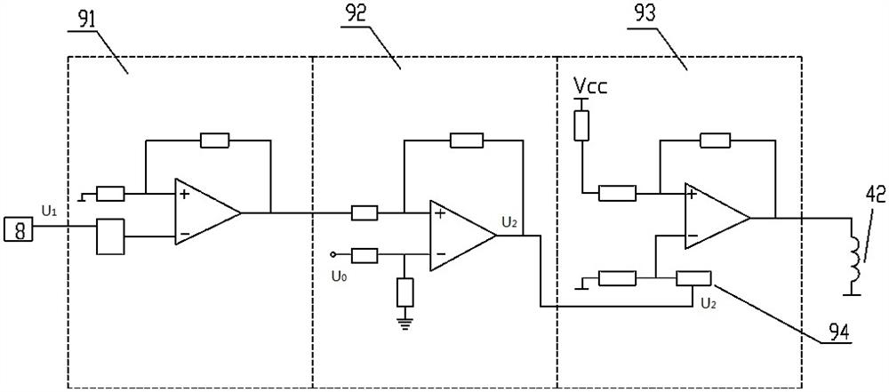
The invention relates to the technical field of electrified railway locomotives, and discloses a magnetic repulsion type suspension pantograph, which includes a base, a bow head bracket and a carbon slide plate, the carbon slide plate is arranged on the bow head bracket, and the base is installed to drive the bow head bracket to rise and fall The electromagnetic mechanism includes an inner cylinder, an outer cylinder, a permanent magnet and an iron core. The carbon slide plate is set on the outer top of the outer cylinder, the inner cylinder is fixed on the base, the permanent magnet is set on the outer cylinder, the iron core is set on the inner cylinder, and the iron A solenoid is wound on the core, a control circuit board for controlling the excitation current in the solenoid is arranged on the base, and a pressure sensor is arranged inside the outer cylinder. The beneficial effects of the present invention are: the pressure sensor is used to monitor the pantograph-catenary contact pressure in real time, and feeds back to the control circuit board, and the control circuit board adjusts the excitation current according to the pressure value and the built-in control algorithm to ensure that the pantograph-catenary contact force is stable at the setting value, so as to ensure the pantograph-catenary flow quality.

Description

technical field [0001] The invention relates to the technical field of electrified railway locomotives, in particular to a magnetic repulsion type suspension pantograph. Background technique [0002] The main structure of the current pantograph is a double four-bar linkage mechanism. When the bow is raised, the solenoid valve of the bow is energized, and the expansion and deformation of the air bag drives the movement of the arm; when the bow is lowered, the solenoid valve is de-energized, the compressed air pressure in the air bag is reduced, and the pantograph falls down by its own gravity; During the work of the bow, it is difficult to actively and real-time control the lifting and lowering of the height of the bow head in a small range. When the contact pressure between the pantograph sliding plate and the catenary is not suitable, offline or too large, it is difficult to actively adjust the bow head. Lift to achieve a stable and continuous ideal contact pressure and co...

Claims


Application Information

Patent Timeline
Patent Type & Authority Patents(China)
IPC IPC(8): B60L5/28B60L5/20
CPCB60L5/28B60L5/205
Inventor 吴欣洲
Owner SOUTHWEST JIAOTONG UNIV
Why Eureka
Try Eureka