Method, device and system for on-line measurement of flue gas flow velocity of kiln smoke exhaust pipeline

A technology of flue gas flow rate and exhaust pipes, which is applied in the direction of furnaces, furnace components, lighting and heating equipment, etc., can solve the problems that the flue gas flow rate of kiln exhaust pipes cannot be measured online and affects the efficiency of heat recovery systems, etc., to achieve reduction Reduce energy consumption, improve accuracy, and improve recycling effects

Pending Publication Date: 2022-05-06
景德镇市市场监督管理综合检验检测中心
View PDF0 Cites 0 Cited by
  • Summary
  • Abstract
  • Description
  • Claims
  • Application Information

AI Technical Summary

Problems solved by technology

[0005] Aiming at the deficiencies of the prior art, the present invention provides an online measurement method, device and system for the flue gas flow rate of the kiln exhaust pipe, which solves the current technology that the flue gas flow rate of the kiln exhaust pipe cannot be measured online and affects the efficiency of the heat recovery system The problem is to achieve the purpose of measuring the flue gas flow rate in the kiln exhaust pipe in real time online, so that the flow rate of the flue gas can be displayed in real time according to the demand, and at the same time, the flow rate measurement of the flue gas is automatically completed at a certain interval, thereby improving the The stable state of the heat recovery system of the kiln improves the recovery and utilization of the heat in the flue gas by the heat recovery system, thereby reducing the energy consumption of the kiln

Method used


Image

  • Method, device and system for on-line measurement of flue gas flow velocity of kiln smoke exhaust pipeline
  • Method, device and system for on-line measurement of flue gas flow velocity of kiln smoke exhaust pipeline
  • Method, device and system for on-line measurement of flue gas flow velocity of kiln smoke exhaust pipeline

Examples


Embodiment 1

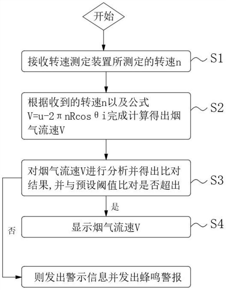
[0053] Please refer to Figure 1-3 , the present embodiment shows an online method for measuring the flue gas flow rate of a kiln exhaust pipe, comprising the following steps:

[0054] Step S1, receiving the rotational speed n measured by the rotational speed measuring device, the rotational speed n is recorded by the rotational speed sensor within the time period every 3-5 minutes, and measured once every 5-10 minutes;

[0055] Step S2, calculate the flue gas flow rate V according to the received rotational speed n, and send it to the terminal. The flue gas flow rate V is obtained according to the calculation formula:

[0056] V=u-2πnRcosθi;

[0057] In the formula, u is assumed to be a constant value of the flue gas flow rate in the flue, n is the rotational speed of the smoke cup, R is the radius from the smoke cup to the rotation axis, and iθ is the intersection angle between the smoke and the normal direction inside the smoke cup;

[0058] Step S3: Analyze the smoke flo...

Embodiment 2

[0075] Please refer to Figure 1-4 , the present embodiment shows an online method for measuring the flue gas flow rate of a kiln exhaust pipe, comprising the following steps:

[0076] Step S1, receiving the rotational speed n measured by the rotational speed measuring device, the rotational speed n is recorded by the rotational speed sensor within the time period every 3-5 minutes, and measured once every 5-10 minutes;

[0077] Step S2, calculate the flue gas flow rate V according to the received rotational speed n, and send it to the terminal. The flue gas flow rate V is obtained according to the calculation formula:

[0078] V=u-2πnRcosθi;

[0079] In the formula, u is assumed to be a constant value of the flue gas flow rate in the flue, n is the rotational speed of the cup, R is the radius from the cup to the rotation axis, and iθ is the angle between the smoke and the normal direction inside the cup;

[0080] Step S3, analyzing the flue gas flow rate V and obtaining the...

Embodiment 3

[0101] Please refer to Figure 5-8 , this embodiment shows a rotating speed measuring device used in the flue of a kiln, including position measuring points set in the flue 20, the number of position measuring points is set to four, and the four position measuring points are respectively set in the flue On the four endpoints of the rectangular boundary formed in the duct 20, the measuring point is used to install the rotational speed measuring device, and the measuring point is set on the vertical section in the flue 20;

[0102] The rotating speed measurement device includes a sampling smoke inlet housing 2011 fixed on the measuring point, a rotating shaft 2012 is installed in the sampling smoke inlet housing 2011, and a plurality of equidistantly distributed blades 2014 are arranged on the outer surface of the rotating shaft 2012 , a tobacco cup 2015 is provided on the leaf plate 2014;

[0103] The rotational speed measuring device further includes a rotational speed sensor...


PUM


Abstract

The invention relates to the technical field of flue gas flow velocity measurement of a kiln smoke exhaust pipeline, solves the technical problems that the flue gas flow velocity of the existing kiln smoke exhaust pipeline cannot be measured on line and the efficiency of a heat recovery system is influenced, and particularly relates to an on-line measurement method for the flue gas flow velocity of the kiln smoke exhaust pipeline. Receiving the rotating speed n measured by the rotating speed measuring device; s2, completing calculation according to the received rotating speed n to obtain the flue gas flow velocity V; s3, the flue gas flow velocity V is analyzed, and a comparison result is obtained; and S4, displaying the flue gas flow velocity V. According to the invention, the purpose of measuring the flow velocity of the flue gas in the kiln smoke exhaust pipeline online in real time is achieved, the flow velocity of the flue gas can be displayed in real time according to requirements, and meanwhile, the flow velocity of the flue gas can be automatically measured at certain intervals, so that the stable state of a kiln heat recovery system is improved, and the working efficiency is improved. Recycling of heat in the flue gas by the heat recovery system is improved, and then energy consumption of the kiln is reduced.

Description

technical field [0001] The invention relates to the technical field of measuring the flue gas velocity of a kiln exhaust pipe, in particular to an on-line measurement method, device and system for the flue velocity of a kiln exhaust pipe. Background technique [0002] At present, during the use of the kiln, the flue gas emitted by the kiln needs to meet the national flue gas emission standards, and the heat is recovered and utilized through the heat recovery system, and then the kiln flue gas that has been purified again is converted from the flue gas discharge to the outside. [0003] Among them, the flow velocity of the kiln flue gas in the exhaust pipe has an mutual influence on the heat recovery system. Therefore, in the heat recovery system, the flue gas flow rate mainly depends on the economy and safety of the heating surface, and the flue gas flow rate is low. , more heating surfaces should be arranged, and the fly ash pollution on the heating surface will be aggrava...

Claims


Application Information

Patent Timeline
Patent Type & Authority Applications(China)
IPC IPC(8): F27D17/00F27D21/04
CPCF27D17/004F27D21/04
Inventor 林娜刘翰承王国建郑驰阳叶加平胡卓异罗宸丁俊华
Owner 景德镇市市场监督管理综合检验检测中心
Why Eureka
Try Eureka