
Dry-type transformer with improved heat dissipation

A technology for dry-type transformers and heat sinks, applied in transformer/inductor magnetic cores, transformer/inductor cooling, transformer/inductor shells, etc., can solve the problems of affecting the service life of dry-type transformers, uneven external shape, and top heat dissipation Poor effect and other problems, to achieve the effect of increasing the contact area, increasing heat transfer, and accelerating heat dissipation

Pending Publication Date: 2022-05-06
白军军
View PDF0 Cites 1 Cited by
  • Summary
  • Abstract
  • Description
  • Claims
  • Application Information

AI Technical Summary

Problems solved by technology

[0004] However, forced air cooling often uses fans to directly dissipate heat from the heat dissipation holes on the outer wall and inside of the dry-type transformer. However, due to the high waste heat generated by the dry-type transformer, the energy carried by the wind when blowing from the bottom side to the fixed measurement is continuously accumulated. This makes the heat dissipation effect of the top poor, especially in the inner side of the high-voltage coil, the heat removed is close to the heat generated, which affects the overall service life of the dry-type transformer, and the cooling fan of the existing dry-type transformer generally has a fixed wind direction type, and the uneven external shape of the dry-type transformer will reduce the heat dissipation efficiency of the fan to the dry-type transformer

Method used


Image

  • Dry-type transformer with improved heat dissipation
  • Dry-type transformer with improved heat dissipation
  • Dry-type transformer with improved heat dissipation

Examples


Embodiment Construction

[0031] The following will clearly and completely describe the technical solutions in the embodiments of the present invention in conjunction with the accompanying drawings in the embodiments of the present invention; obviously, the described embodiments are only part of the embodiments of the present invention, not all embodiments, based on The embodiments of the present invention and all other embodiments obtained by persons of ordinary skill in the art without making creative efforts belong to the protection scope of the present invention.

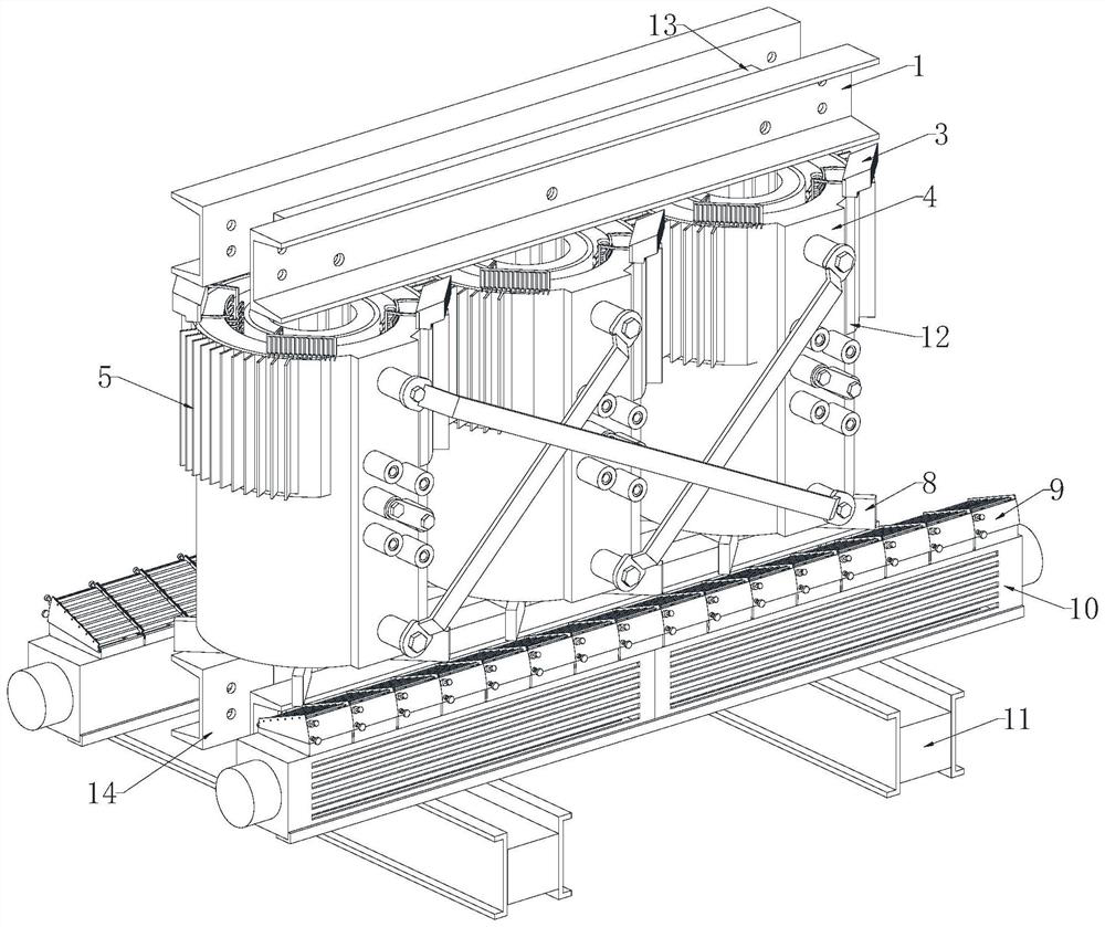
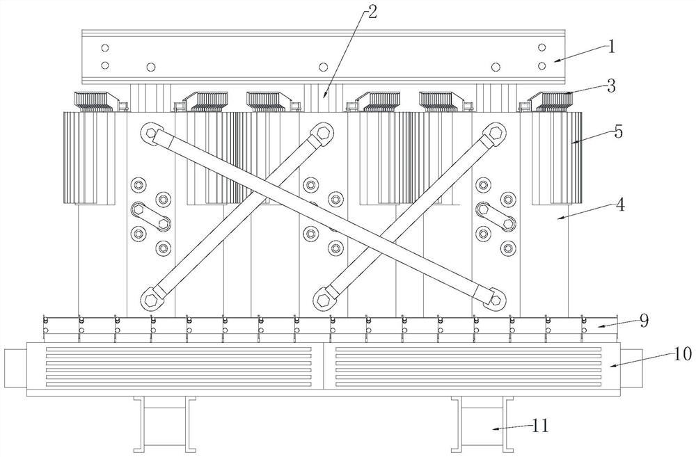
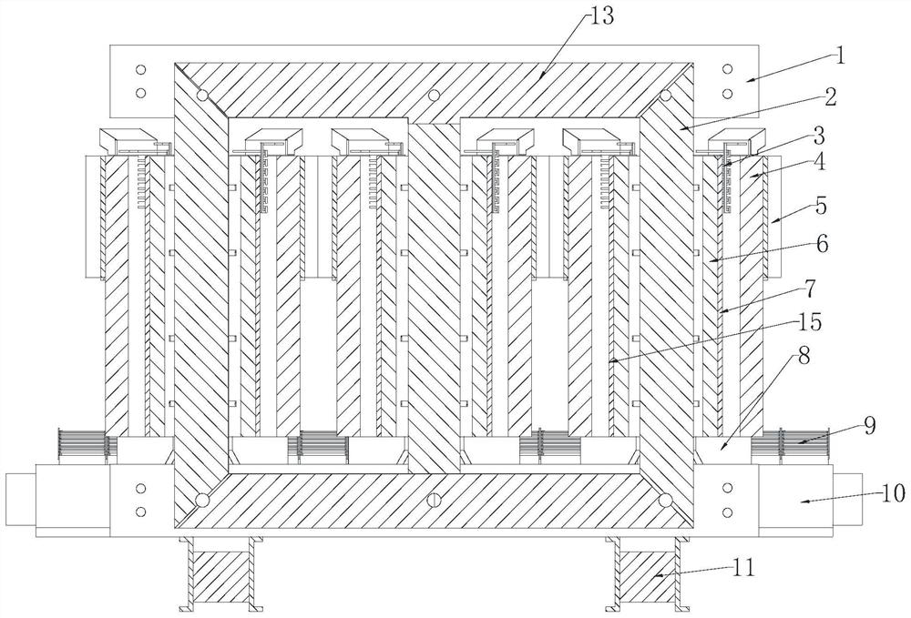
[0032] see Figure 1-11 , a dry-type transformer with improved heat dissipation, comprising a vertical iron core 2, the top and bottom of the vertical iron core 2 are fixedly connected with a horizontal iron core 13, and the two ends of the horizontal iron core 13 are respectively fixedly connected with a fixing frame 1 and the fixed frame two 14, the bottom of the fixed frame two 14 is fixedly connected with a support column 11, and the...


PUM


Abstract

The invention discloses a dry-type transformer with improved heat dissipation, and relates to the technical field of dry-type transformers, and the dry-type transformer is characterized in that the dry-type transformer comprises a vertical iron core, the top and the bottom of the vertical iron core are fixedly connected with a transverse iron core, and the two ends of the transverse iron core are fixedly connected with a fixing frame and a second fixing frame respectively; a supporting column is fixedly connected to the bottom of the second fixing frame, fans are fixedly connected to the positions, located at the two ends of the high-voltage coil, of the top of the supporting column, wind direction adjusting devices are fixedly connected to the tops of the fans, and the vertical iron core is sequentially sleeved with a low-voltage coil, an insulating sleeve and the high-voltage coil. A heat dissipation gap exists between the high-voltage coil and the insulating sleeve, and the top of the second fixing frame is fixedly connected with supporting partition plates which are distributed on the outer side of the vertical iron core in an array mode. The dry-type transformer has the advantages that heat in the dry-type transformer can be transferred to the outer wall to facilitate heat dissipation, and the wind direction of the fan can be adjusted to enable wind blown by the fan to more effectively dissipate heat of the dry-type transformer.

Description

technical field [0001] The invention relates to the technical field of dry-type transformers, in particular to a dry-type transformer with improved heat dissipation. Background technique [0002] Dry-type transformers are widely used in local lighting, high-rise buildings, airports, wharf CNC mechanical equipment and other places. Simply put, dry-type transformers refer to transformers whose iron core and windings are not immersed in insulating oil. [0003] Cooling methods are divided into natural air cooling (AN) and forced air cooling (AF). When naturally air-cooled, the transformer can operate continuously for a long time at the rated capacity. When forced air cooling, the output capacity of the transformer can be increased by 50%. It is suitable for intermittent overload operation, or emergency accident overload operation; due to the large increase in load loss and impedance voltage during overload, it is in a non-economic operation state, so it should not be used for...

Claims


Application Information

Patent Timeline
IPC IPC(8): H01F27/08H01F27/10H01F27/26H01F27/30H01F27/02
CPCH01F27/08H01F27/10H01F27/266H01F27/306H01F27/02
Inventor 白军军
Owner 白军军
Learn More