Self-cleaning efficient machining numerical control machine tool

A CNC machine tool, self-cleaning technology, applied in metal processing equipment, grinding machine parts, manufacturing tools, etc., can solve problems such as affecting service life, difficult to clean, equipment pollution, etc.

Pending Publication Date: 2022-05-10
ANHUI SCI & TECH UNIV
View PDF0 Cites 0 Cited by
  • Summary
  • Abstract
  • Description
  • Claims
  • Application Information

AI Technical Summary

Problems solved by technology

[0003] In the process of machining workpieces by CNC machine tools, it is necessary to use cooling liquid to flush the polished milling cutter part to facilitate the heat dissipation of the milling cutter part, but the sprayed liquid will directly enter the surface of the machine body, which will cause equipment It is polluted to a certain extent, and in the process of workpiece processing, certain debris will be generated, which is very easy to mix with the leaked coolant, which makes it difficult to clean, and CNC machine tools generally use manual cleaning of the surface Cleaning up requires a certain amount of manpower, and because the CNC machine tool is made of metal materials, personal injury accidents are prone to occur during the cleaning process, and if the CNC machine tool has not been cleaned for a long time, the debris generated on the surface Chips and coolant may cause equipment to be corroded to a certain extent, and then lead to certain economic losses; in addition, the existing machine tools are manually operated in the process of clamping the workpiece, and the degree of automation is low. , in the process of separating coolant and debris, the screening plate is rigidly vibrating, which seriously affects the service life, so there is an urgent need for a fully automatic cleaning CNC machine tool in the market

Method used


Image

  • Self-cleaning efficient machining numerical control machine tool
  • Self-cleaning efficient machining numerical control machine tool
  • Self-cleaning efficient machining numerical control machine tool

Examples


Embodiment Construction

[0037] The technical solutions in the present invention will be clearly and completely described below in conjunction with the accompanying drawings in the present invention. In addition, the forms of the structures described in the following embodiments are only examples. The self-cleaning The high-efficiency machining CNC machine tool is not limited to the structures described in the following embodiments, and all other embodiments obtained by those skilled in the art without creative work fall within the protection scope of the present invention.

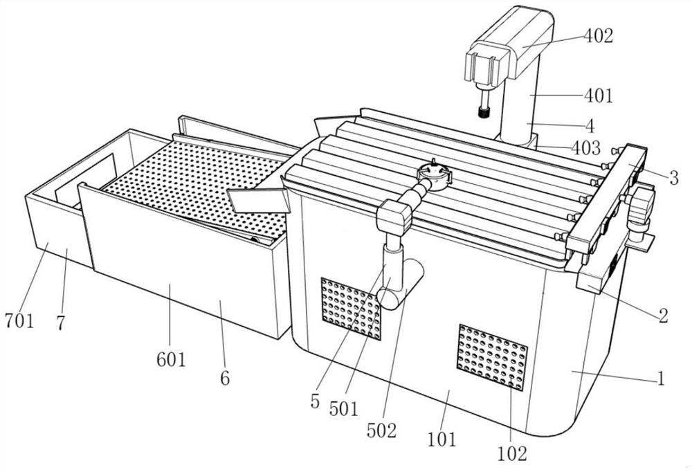
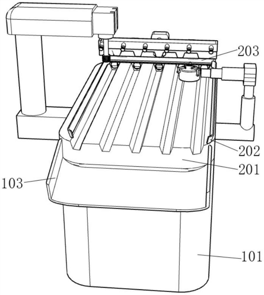
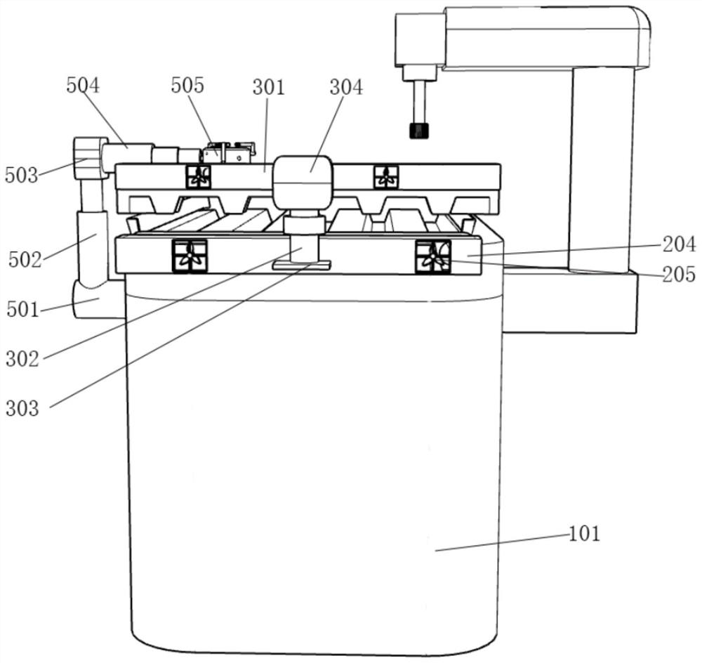
[0038] The present invention provides a self-cleaning high-efficiency CNC machine tool, including a machine tool mechanism 1, a blowing mechanism 2, a cleaning mechanism 3, a polishing mechanism 4, a fixing mechanism 5, a classification mechanism 6, and a storage mechanism 7, and also includes:

[0039] The blowing mechanism 2 is arranged on the top side of the machine tool mechanism 1, and the blowing mechanism 2 is fixedly conne...


PUM


Abstract

The invention relates to the technical field of numerical control machine tools, and discloses a self-cleaning efficient machining numerical control machine tool which is characterized in that one end of an electromagnetic lifting column is fixedly connected with a first supporting seat, one end of the first supporting seat is fixedly connected with a first automatic hydraulic column, and one end of the first automatic hydraulic column is fixedly connected with a cleaning cabin; a second fan blade set is fixedly connected to the inner wall of one end of the cleaning cabin, and an air blowing gun opening is fixedly connected to the inner wall of the other end of the cleaning cabin. By arranging a lifting fixing plate, the effect of fixing the whole cleaning mechanism is achieved, by arranging an electromagnetic lifting column, the effect of providing lifting force is achieved, and by arranging a first supporting seat, the cleaning mechanism is convenient to use. And by arranging a first fan blade set and a first automatic hydraulic column, fixing of the first automatic hydraulic column is facilitated, by arranging a cleaning cabin, a second fan blade set and an air blowing muzzle, generation and transmission of wind power are facilitated, and by arranging a sliding scraping plate and a sponge plate, cleaning of impurities and cooling liquid on the surface of equipment is facilitated.

Description

technical field [0001] The invention relates to the technical field of numerical control machine tools, more specifically, the invention relates to a self-cleaning high-efficiency machining numerical control machine tool. Background technique [0002] Numerical control machine tool is the abbreviation of digital control machine tool, which is an automatic machine tool equipped with a program control system, which can logically process programs with control codes or other symbolic instructions, and decode them, using coded numbers It means that the numerical control device is input through the information carrier, and various control signals are sent out by the numerical control device after calculation and processing to control the movement of the machine tool, and automatically process the workpiece according to the shape and size required by the drawing. [0003] In the process of machining workpieces by CNC machine tools, it is necessary to use cooling liquid to flush the...

Claims


Application Information

Patent Timeline
IPC IPC(8): B24B3/02B24B3/00B24B41/06B24B47/00B24B47/22B24B55/06B24B41/00B01D33/03B01D33/80
CPCB23Q11/005B23Q11/0067B23Q11/0042B23Q3/06Y02P70/10
Inventor 陶浩浩李同杰陈丰张立勇余振
Owner ANHUI SCI & TECH UNIV
Why Eureka
Try Eureka