Hollow rod watering viscosity reduction device

A hollow rod and viscosity reduction technology, applied in the field of hollow rods, can solve the problems of inconvenient hot water constant temperature, reduced viscosity reduction efficiency, inconvenience of crude oil reflux, etc., to achieve the effect of avoiding uneven water temperature, reducing viscosity reduction efficiency, and simple structure

Pending Publication Date: 2022-05-10
DONGYING BAOYE GASOLINEEUM TECH DEV
View PDF0 Cites 0 Cited by
  • Summary
  • Abstract
  • Description
  • Claims
  • Application Information

AI Technical Summary

Problems solved by technology

[0004] The purpose of the present invention is to solve the problem of the inconvenience of maintaining a constant temperature of hot water during the use of the hollow rod mixed with water viscosity reducing device in the prior art, which will lead to uneven water temperature and reduce the viscosity reducing efficiency, and it is inconvenient to prevent crude oil from flowing back, thereby The shortcoming that the hollow rod is prone to clogging, and a hollow rod mixed with water viscosity reduction device is proposed

Method used


Image

  • Hollow rod watering viscosity reduction device
  • Hollow rod watering viscosity reduction device
  • Hollow rod watering viscosity reduction device

Examples


Embodiment 1

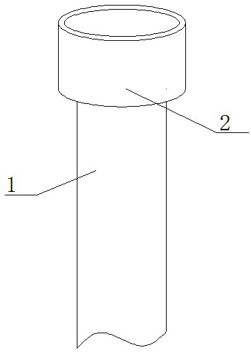
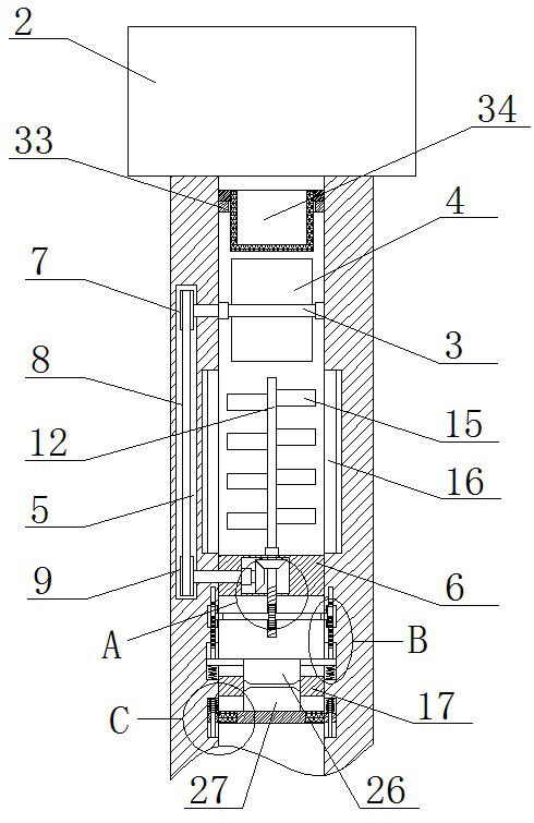
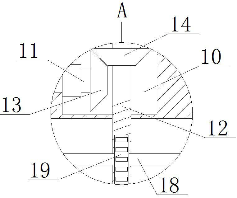
[0026] refer to Figure 1-5 , the hollow rod mixed with water viscosity reducing device, comprising a hollow rod body 1, one end of the hollow rod body 1 is fixedly connected with a water inlet 2 by welding, a first hollow groove 5 is opened in the hollow rod body 1, and the inner wall of the hollow rod body 1 is opened There is a first through hole, and the first rotating shaft 3 is installed in rotation in the first through hole, and two symmetrical water barriers 4 are fixedly installed on the first rotating shaft 3 by welding, and the installation rod 6 is fixedly installed in the hollow rod body 1 by welding , the mounting rod 6 is provided with a second vacant slot 10, a stirring heating mechanism is arranged in the second vacant slot 10, and a second through hole is provided on one side inner wall of the second vacant slot 10, and the second through hole is connected with the first vacant slot 5 communicate with each other, the second rotating shaft 11 is installed in t...

Embodiment 2

[0035] The difference from Embodiment 1 is that one end of the hollow rod body 1 is fixedly connected with the water inlet 2 by welding, the hollow rod body 1 is provided with a first hollow groove 5, and the inner wall of the hollow rod body 1 is provided with a first through hole , the first rotating shaft 3 is installed in rotation in the first through hole, and two symmetrical water shields 4 are fixedly installed on the first rotating shaft 3 by welding, and a limit ring 33 is fixedly installed in the hollow rod body 1. A filter screen 34 is placed, and the installation rod 6 is fixedly installed by welding in the hollow rod body 1. A second empty groove 10 is provided in the installation rod 6, and a stirring and heating mechanism is arranged in the second empty groove 10. One of the second empty groove 10 The side inner wall is provided with a second through hole, the second through hole communicates with the first empty groove 5, the second rotating shaft 11 is installe...


PUM


Abstract

The invention belongs to the field of hollow rods, particularly relates to a hollow rod watering viscosity reduction device, and aims to solve the problems that the viscosity reduction efficiency is reduced due to non-uniform water temperature caused by inconvenience in keeping constant temperature of hot water in the using process of an existing hollow rod watering viscosity reduction device, and the hollow rod is easy to block due to inconvenience in preventing backflow of crude oil. According to the scheme, the device comprises a hollow rod body, one end of the hollow rod body is fixedly connected with a water inlet through welding, a first empty groove is formed in the hollow rod body, a first through hole is formed in the inner wall of the hollow rod body, the first through hole is communicated with the first empty groove, and a first rotating shaft is rotationally installed in the first through hole; in the using process, the constant temperature of hot water can be conveniently kept, the viscosity reduction efficiency can be prevented from being reduced due to uneven water temperature, crude oil backflow can be conveniently prevented, the hollow rod can be prevented from being blocked, the structure is simple, and use is convenient.

Description

technical field [0001] The invention relates to the technical field of hollow rods, in particular to a hollow rod water-mixed viscosity reducing device. Background technique [0002] An oil field refers to the sum of oil and gas reservoirs in the same oil and gas production area under the control of a single geological structure (or formation) factor; an oil well is a hole drilled for oil production and a well layout system according to the oil field development plan, and oil rises from the bottom of the well to Wellhead channel. In the production process of heavy oil wells in oil fields, some oil wells have high wax content, which is easy to precipitate and adhere to the inner wall of the oil pipe or the sucker rod on the upper part of the oil sucker pipe, causing channel blockage, and the downward movement of the sucker rod is blocked, so the wax has to be removed regularly. At present, wax removal generally adopts injecting hot water into the hollow sucker rod for viscos...

Claims


Application Information

Patent Timeline
Patent Type & Authority Applications(China)
IPC IPC(8): E21B17/00E21B43/20E21B43/24E21B43/25
CPCE21B17/00E21B43/20E21B43/2401E21B43/25
Inventor 高鹏王超刘皓中韩封兰浩天
Owner DONGYING BAOYE GASOLINEEUM TECH DEV
Why Eureka
Try Eureka