High-temporal-spatial-resolution full-field heat release rate measurement method and system

A technology of spatiotemporal resolution and heat release rate, applied in the field of optical measurement, can solve problems such as the inability to solve the heat release rate alone, and achieve the effect of alleviating the insufficient resolution of heat release rate measurement and obtaining accurate measurement results.

Active Publication Date: 2022-05-10
BEIHANG UNIV
View PDF5 Cites 3 Cited by
  • Summary
  • Abstract
  • Description
  • Claims
  • Application Information

AI Technical Summary

Problems solved by technology

However, due to the unknown local sound velocity, this method can only solve the law of relative amplitude variation, and cannot solve the heat release rate alone

Method used


Image

  • High-temporal-spatial-resolution full-field heat release rate measurement method and system
  • High-temporal-spatial-resolution full-field heat release rate measurement method and system
  • High-temporal-spatial-resolution full-field heat release rate measurement method and system

Examples


Embodiment 1

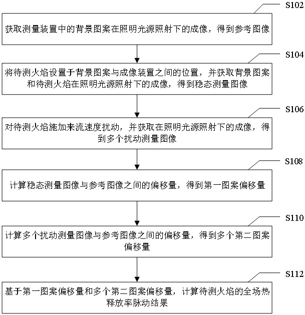
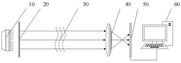
[0023] figure 1 It is a flowchart of a method for measuring full-field heat release rate with high spatiotemporal resolution according to an embodiment of the present invention, and the method is applied to a measuring device provided in an embodiment of the present invention. specific, figure 2 is a schematic diagram of a measuring device provided according to an embodiment of the present invention, such as figure 2 As shown, the device includes: an illumination source 10 , a background pattern 20 and an imaging device 40 . Optionally, as in figure 2 As shown, the measuring device also includes an image sensor 50 and a processing device 60 .

[0024] Wherein, the illumination light source 10 , the background pattern 20 , the imaging device 40 and the image sensor 50 are sequentially arranged on the same straight line; the flame 30 to be measured is arranged at a position between the background pattern 20 and the imaging device 40 .

[0025] Optionally, in the embodimen...

Embodiment 2

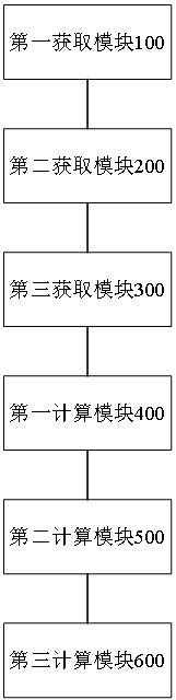
[0062] image 3 is a schematic diagram of a full-field heat release rate measurement system with high temporal and spatial resolution according to an embodiment of the present invention. Such as image 3 As shown, the system includes: a first acquisition module 100 , a second acquisition module 200 , a third acquisition module 300 , a first calculation module 400 , a second calculation module 500 and a third calculation module 600 .

[0063] Specifically, the first acquisition module 100 is configured to acquire the imaging of the background pattern in the measurement device under the illumination of the illumination light source to obtain a reference image.

[0064] Wherein, the background pattern is a pattern generated based on the Poisson disk sampling method; the measurement device includes: an illumination source, a background pattern and an imaging device, wherein the illumination source, the background pattern, and the imaging device are sequentially arranged on the sa...


PUM


Abstract

The invention provides a high-temporal-spatial-resolution full-field heat release rate measurement method and system, and relates to the technical field of optical measurement, and the method comprises the steps: obtaining a reference image of a background pattern in a measurement device under the irradiation of an illumination light source; arranging a to-be-measured flame at a position between the background pattern and the imaging device, and obtaining a steady-state measurement image of the background pattern and the to-be-measured flame under the irradiation of the illumination light source; applying incoming flow velocity disturbance to the flame to be measured, and obtaining a plurality of disturbance measurement images under the irradiation of the illumination light source; calculating a first pattern offset between the steady-state measurement image and the reference image; calculating a plurality of second pattern offsets between the plurality of disturbance measurement images and the reference image; and calculating a full-field heat release rate pulsation result of the flame to be detected based on the first pattern offset and the plurality of second pattern offsets. According to the invention, the technical problem of insufficient measurement resolution of the heat release rate caused by limitation of measurement conditions in the prior art is relieved.

Description

technical field [0001] The invention relates to the technical field of optical measurement, in particular to a method and system for measuring full-field heat release rate with high temporal and spatial resolution. Background technique [0002] The measurement of flame heat release rate is an important issue in the field of aerospace engines, which plays an important role in optimizing the structural design of rocket engines and studying the mechanism of unstable combustion of engines. There are two main methods for measuring the existing optical heat release rate: the processing method based on the light intensity of chemiluminescence and the laser interference processing method. [0003] The processing method based on light intensity usually uses a high-speed camera or a photomultiplier tube combined with a CH filter to record the flame chemiluminescence intensity I, and the disturbance of the received luminous intensity is considered to be proportional to the disturbance ...

Claims


Application Information

Patent Timeline
Patent Type & Authority Applications(China)
IPC IPC(8): G01J5/20G01J5/48G01K17/00G01M15/14G01N25/22
CPCG01J5/20G01J5/0018G01K17/003G01N25/22G01M15/14G01J2005/0077G01J2005/204
Inventor 杨立军李敬轩张玥梁炫烨徐旭宋艳田雨
Owner BEIHANG UNIV
Why Eureka
Try Eureka