OPC correction method

An extension direction, isolated line technology, applied in the field of optical proximity effect correction, can solve the problems such as pitchloose can not be completely solved, poor process window in the middle area, easy disconnection and other problems, to avoid adverse effects, prevent easy disconnection, and improve process window. Effect

Pending Publication Date: 2022-05-10
SHANGHAI HUALI INTEGRATED CIRCUTE MFG CO LTD
View PDF0 Cites 2 Cited by
  • Summary
  • Abstract
  • Description
  • Claims
  • Application Information

AI Technical Summary

Problems solved by technology

[0006] However, in the case of multiple quasi-isolated line ends, that is, semi-isolated line ends, aligned on one line, due to the optical / photoresistive phenomenon of shortened line ends, the line ends need to be corrected a lot outward, and the aligned line ends will be generated during OPC correction. Simultaneous external expansion and mutual conflict, resulting in serious squeeze on the dense graphic area in the middle from both sides, so that pitch loose cannot completely solve the problem of poor process window and easy disconnection in the middle area

Method used


Image

  • OPC correction method
  • OPC correction method
  • OPC correction method

Examples


Embodiment O

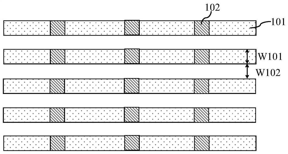
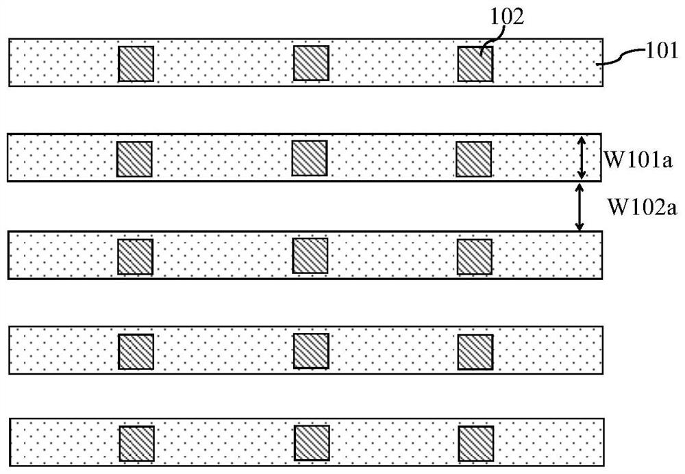
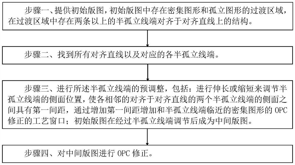
[0039] Such as figure 2 Shown is the flow chart of the OPC correction method of the embodiment of the present invention; as Figure 3A to Figure 3DAs shown, it is a schematic diagram of graphics aligned with various semi-isolated line ends 202 in the original layout of the OPC correction method according to the embodiment of the present invention; Figure 4A to Figure 4C As shown, it is a schematic diagram of the graph when pre-adjusting various semi-isolated line ends 202 by using the elongation method in the OPC correction method of the embodiment of the present invention; Figure 5A to Figure 5C Shown is a schematic diagram of the OPC correction method of the embodiment of the present invention when various semi-isolated line ends 202 are pre-adjusted by using a shortening method; the OPC correction method of the embodiment of the present invention includes the following steps:

[0040] Step 1, such as Figure 3A to Figure 3D As shown, it is a schematic diagram of graphi...


PUM


Abstract

The invention discloses an OPC (Optical Proximity Correction) method, which comprises the following steps of: 1, providing an original layout in which a transition region of dense graphs and isolated graphs exists, and in which more than two structures with semi-isolated line ends aligned to aligned straight lines exist; 2, finding all aligned straight lines and corresponding semi-isolated line ends; step 3, pre-adjusting the semi-isolated line ends, namely, extending or shortening to adjust the side surface positions of the semi-isolated line ends, so that a first distance is formed between the side surfaces of two adjacent semi-isolated line ends aligned to the aligned straight line, and a second distance is formed between the side surfaces of two adjacent semi-isolated line ends aligned to the aligned straight line; increasing a process window of OPC correction of the dense pattern close to the semi-isolated line end by increasing the first interval; the original layout becomes an intermediate layout after being subjected to semi-isolated line end adjustment; and 4, carrying out OPC correction on the intermediate layout. According to the invention, the OPC process window of the dense pattern close to the semi-isolated line end alignment position can be improved.

Description

technical field [0001] The invention relates to a semiconductor integrated circuit manufacturing method, in particular to an optical proximity correction (OPC) method. Background technique [0002] In the photolithography process, the pattern structure corresponding to the layout on the reticle (Mask) will be projected into the photoresist through the exposure system and form the corresponding pattern structure in the photoresist, but due to the optical The reason or the chemical reaction of the photoresist, there is a deviation between the pattern structure formed in the photoresist and the pattern structure on the mask plate. This deviation needs to be modified in advance on the pattern structure on the mask plate through OPC correction. When the OPC-corrected mask is exposed, the pattern structure formed in the photoresist will be consistent with the designed pattern structure and meet the production requirements of the process. [0003] In the graphic structure of the l...

Claims


Application Information

Patent Timeline
Patent Type & Authority Applications(China)
IPC IPC(8): G03F1/36
CPCG03F1/36
Inventor 李葆轩刘佳琦
Owner SHANGHAI HUALI INTEGRATED CIRCUTE MFG CO LTD
Why Eureka
Try Eureka