
Equipment power supply control method and system
A power control and equipment technology, applied in the transmission system, digital transmission system, electrical components, etc., can solve the problems of unable to detect the power consumption status of farming equipment in real time, complex control system structure and control logic, and high labor cost, etc., to achieve Reduce the risk of electricity consumption, simplify the system structure and control logic, and reduce the effect of labor costs
- Summary
- Abstract
- Description
- Claims
- Application Information
AI Technical Summary
Problems solved by technology
Method used
Image

Examples
Embodiment 1
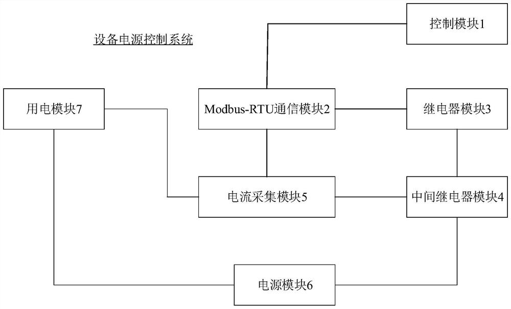
[0047] Embodiment 1 provides a device power control system. Such as figure 1 As shown, the equipment power control system includes a control module 1, a Modbus-RTU communication module 2, a relay module 3, an intermediate relay module 4, a current acquisition module 5, a power module 6 and a power module 7.
[0048] Optionally, the Modbus-RTU communication module 2 is connected to the control module 1, the current acquisition module 5 and the relay module 3 respectively. The intermediate relay module 4 is connected to the current acquisition module 5 , the relay module 3 and the power module 6 respectively. The electricity consumption module 7 is connected with the current acquisition module 5 and the power supply module 6 .
[0049] The working principle of the device power supply control system provided in Embodiment 1 may be as follows:
[0050] After the control module 1 is connected to the Modbus-RTU communication module 2, the control module 1 can send a current query...
Embodiment 2
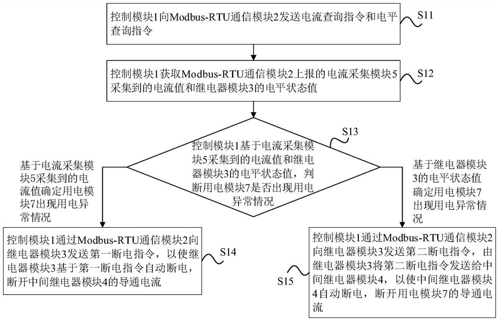
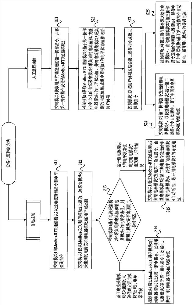
[0071] Embodiment 2 provides a device power control method, which can be applied to the device power control system in Embodiment 1 above. combine Figure 1-2 As shown, the device power control method may include the following steps:
[0072] S11. The control module 1 sends a current query command and a level query command to the Modbus-RTU communication module 2 .
[0073] In a specific implementation process, the current query instruction is used to obtain the current value collected by the current collection module 5 , and the level query instruction is used to obtain the level state value of the relay module 3 .
[0074] In a specific implementation process, the current query command and the level status query command can be Modbus-RTU protocol commands.
[0075] In a specific implementation process, the control module 1 can regularly send the current query command and the level query command to the Modbus-RTU communication module 2 through the RS485 protocol.
[0076] ...
PUM
 Abstract
Description
Claims
Application Information