
Embolism spring ring conveying system

A delivery system and spring coil technology, applied in the field of medical devices, to achieve the effect of reducing the cost of devices, avoiding jamming or breaking, and improving the reliability of release

Pending Publication Date: 2022-05-13
南京思脉德医疗科技有限公司
View PDF11 Cites 9 Cited by
  • Summary
  • Abstract
  • Description
  • Claims
  • Application Information

AI Technical Summary

Problems solved by technology

[0009] The purpose of the present invention is to provide an embolic coil delivery system to solve the problems in the use process of the existing embolic coil delivery system proposed in the background art

Method used


Image

  • Embolism spring ring conveying system
  • Embolism spring ring conveying system
  • Embolism spring ring conveying system

Examples


Embodiment 1

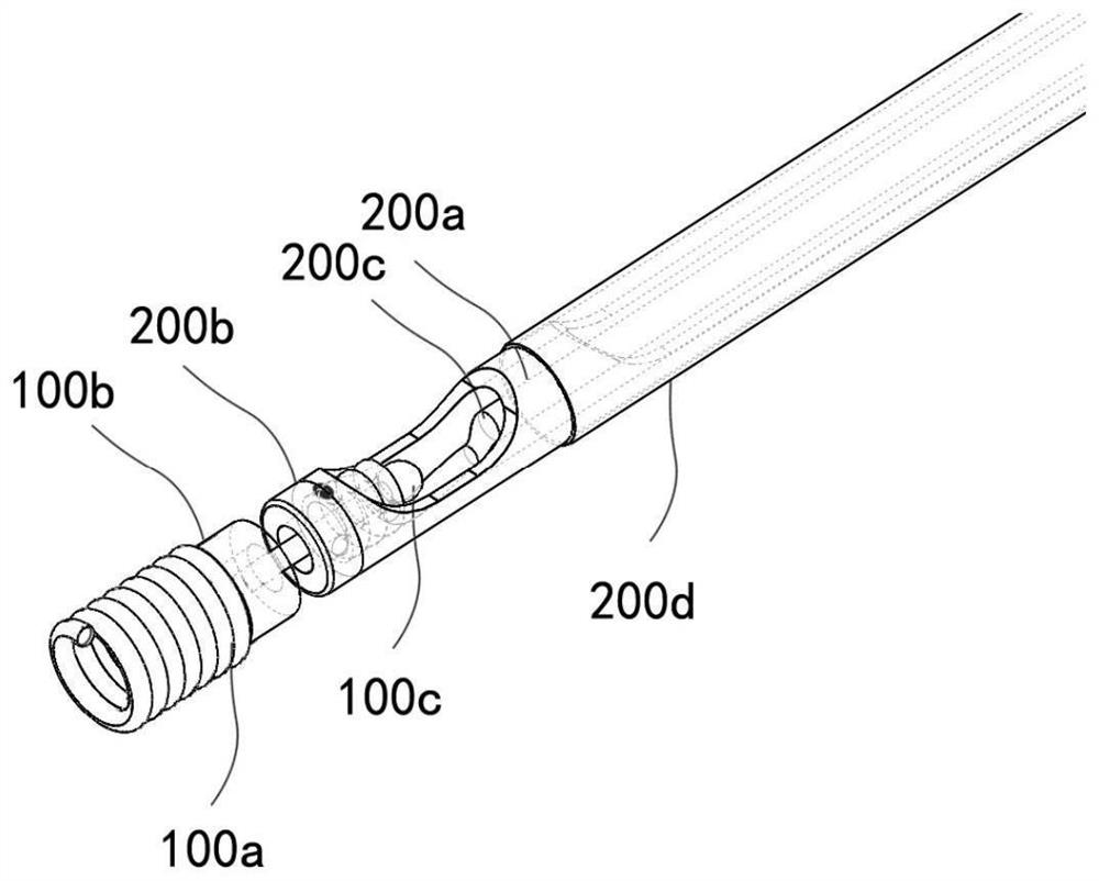
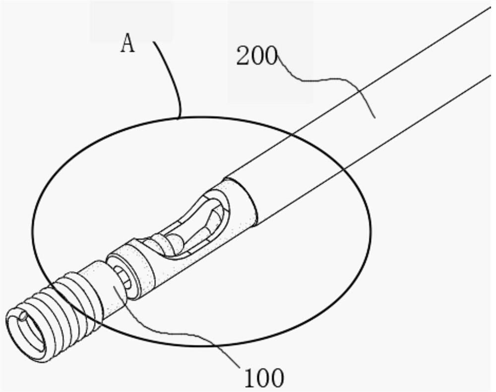
[0048] see Figure 1-6 , the present invention provides a technical solution: an embolic coil delivery system, comprising:

[0049] The implant 100 includes a release component 100c, the rod-shaped part of the release component 100c extends out of the implant 100 and is provided with a spherical head;

[0050] Pushing system 200, comprising release wire 200c, the end of release wire 200c close to implant 100 is wound on release assembly 100c, so as to be detachably mounted on release assembly 100c through a spherical head;

[0051] The break release mechanism 300 is located at the end of the push system 200 away from the implant 100 , and the release wire 200c extends away from the spherical head into the break release mechanism for breaking and separating the implant 100 .

[0052] From the distal end to the proximal end, the pushing system 200 of the implant 100 and the breaking release mechanism 300 are fixedly connected in sequence.

[0053] Specifically, the other end o...

Embodiment 2

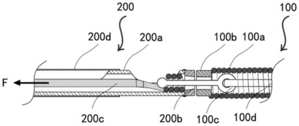
[0075] see Figure 7 , the present invention also provides another technical solution: similar to Embodiment 1, the distal end of the release wire 200c can be made into a conical spring, which is convenient for assembly and improves stability. Figure 7 F in refers to the direction of the force.


PUM


Abstract

The invention discloses an embolism spring ring conveying system, and belongs to the technical field of medical instruments, the embolism spring ring conveying system comprises an implant, the implant comprises a release assembly, and one end, extending out of the implant, of a rod-shaped part of the release assembly is provided with a spherical head; the pushing system comprises a releasing wire, and the end, close to the implant, of the releasing wire is wound around the releasing assembly so that the releasing wire can be detachably installed on the releasing assembly through the spherical head; and the breaking and releasing mechanism is located at the end, far away from the implant, of the pushing system, and the releasing wire far away from the spherical head extends into the breaking and releasing mechanism and is used for breaking to achieve separation of the implant. According to the novel mechanical release structure, the release wire at the far end is detachably connected with the release assembly through the spiral spring-shaped structure, the machining precision and the assembly requirement of parts are lowered, and the release reliability is improved.

Description

technical field [0001] The invention belongs to the technical field of medical devices, and in particular relates to an embolic coil delivery system. Background technique [0002] Percutaneous treatment of various forms of endovascular lesions is an increasingly popular treatment modality. As a common clinical device, embolic coil therapy is increasingly used in volume and scope. From intracranial aneurysms to peripheral blood vessels to tumor treatment, embolic coils play an important role, which can promote thrombus formation, prevent aneurysm bleeding or cut off blood supply to tumors. [0003] Embolic coils typically consist of two parts, including a push system for delivery and a coil for implantation. After percutaneous vascular puncture, the coil is delivered to the predetermined location through a multistage delivery catheter. Taking intracranial implantation as an example, the guiding catheter is first inserted into the puncture sheath, the distal end of the guid...

Claims


Application Information

Patent Timeline
Patent Type & Authority Applications(China)
IPC IPC(8): A61B17/12
CPCA61B17/12031A61B17/12113A61B17/1214A61B2017/12054
Inventor 方晓东裴世宁章仕忠
Owner 南京思脉德医疗科技有限公司
Learn More