Dehydration device and combustion equipment

A technology of dehydration device and combustion equipment, which is applied to combustion equipment, blower equipment, combustion methods, etc., can solve the problems of dampness of combustion equipment and fans, hidden safety hazards of electronic components, and condensed water in the gas supply system, and achieves long service life. , Improve the effect of safe and reliable service cycle and avoid circuit failure

Pending Publication Date: 2022-05-13
WUHU TUNGHSU PHOTOELECTRIC SCI & TECHCO +1
View PDF9 Cites 0 Cited by
  • Summary
  • Abstract
  • Description
  • Claims
  • Application Information

AI Technical Summary

Problems solved by technology

In related technologies, a certain amount of high-temperature combustion flue gas (FGR) is usually added to the combustion-supporting air, so as to reduce the local temperature of the combustion area, and at the same time reduce the concentration of oxygen, thereby reducing the amount of NOx produced, but because FGR needs to Part of the flue gas is mixed with cold air, and when FGR is mixed with cold air, condensed water will be generated, which will cause condensed water in the air supply system, which will cause moisture and water accumulation inside the combustion equipment and fan, and make the electronic components of the combustion equipment have big security risk

Method used


Image

  • Dehydration device and combustion equipment
  • Dehydration device and combustion equipment
  • Dehydration device and combustion equipment

Examples


Embodiment Construction

[0027] Specific embodiments of the present disclosure will be described in detail below in conjunction with the accompanying drawings. It should be understood that the specific embodiments described here are only used to illustrate and explain the present disclosure, and are not intended to limit the present disclosure.

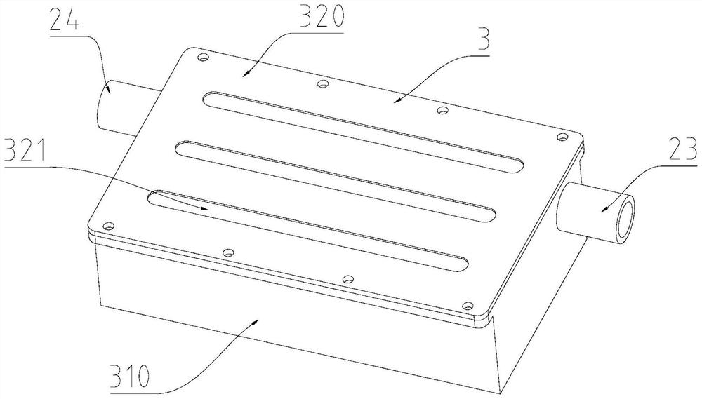
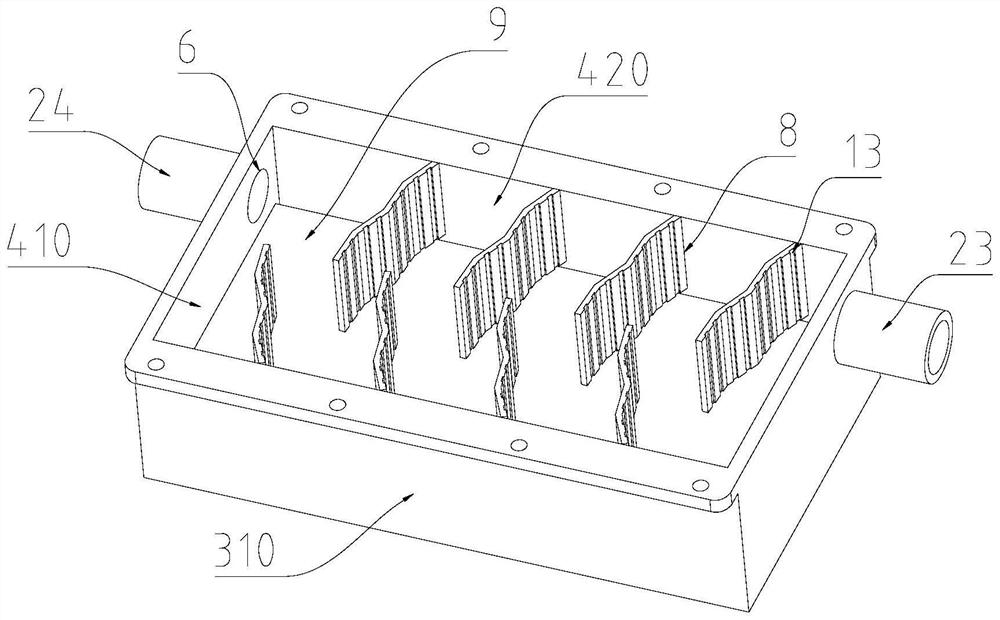
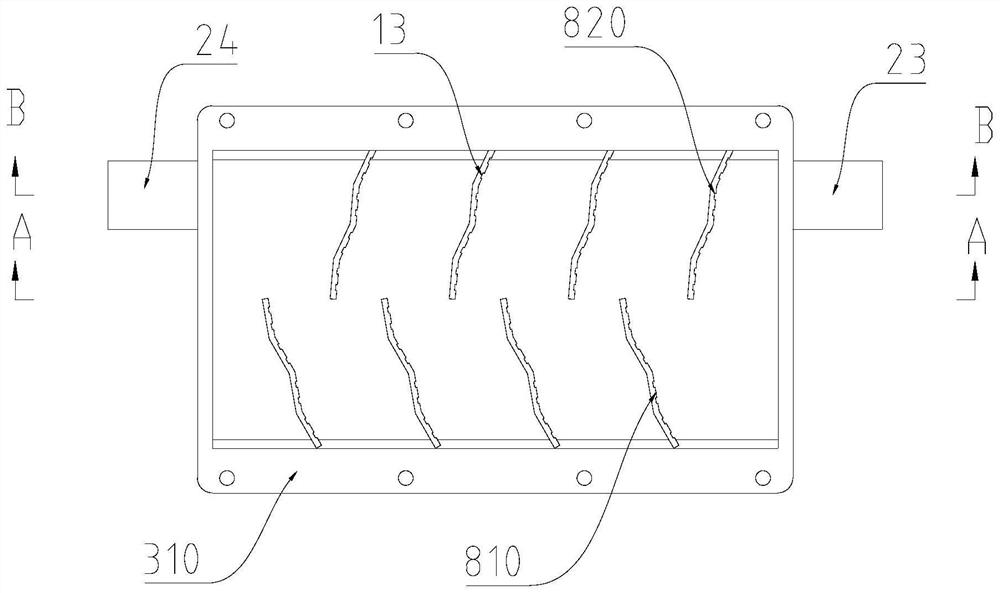
[0028] In this disclosure, unless stated otherwise, the used orientation words such as "up and down" refer to the up and down in the space when the dehydration device is in use, and also refer to Figure 4 to Figure 6 Up and down in the direction of the drawing; "inside and outside" refer to inside and outside relative to the outline of the part or structure itself. In addition, it should be noted that the terms used, such as "first, second", etc., are used to distinguish one element from another, and do not have sequence or importance. In addition, in the description with reference to the drawings, the same symbols in different drawings represent the same e...


PUM


Abstract

The invention relates to a dehydration device and combustion equipment, the dehydration device is used for being arranged between a mixer and an air inlet fan of the combustion equipment, the dehydration device comprises a shell, the shell is provided with a dehydration cavity, an air inlet, an air outlet and a water outlet, the air inlet, the air outlet and the water outlet are communicated with the dehydration cavity, and the air inlet is communicated with an outlet of the mixer; the gas outlet is communicated with an inlet of the gas inlet fan, a dehydration plate assembly is arranged in the dehydration cavity, and the dehydration plate assembly is configured to be capable of forming a snake-shaped flow path horizontally extending from the gas inlet to the gas outlet in the dehydration cavity, so that when the mixed gas flows along the snake-shaped flow path, the mixed gas enters the dehydration cavity; and liquid in the mixed gas can flow to the water outlet to be discharged under the action of gravity. Through the technical scheme, the dehydration device provided by the invention is good in dehumidification effect, can stably work, and has the advantages of long service life, high efficiency and low energy consumption.

Description

technical field [0001] The present disclosure relates to the technical field of gas combustion low-nitrogen emission air supply, in particular to a dehydration device and combustion equipment. Background technique [0002] With the improvement of environmental protection requirements, low nitrogen emission of gas combustion is an important indicator of environmental monitoring, and reducing nitrogen oxide emissions is an effective measure for atmospheric environmental protection, so low nitrogen emission combustion equipment is widely used. In related technologies, a certain amount of high-temperature combustion flue gas (FGR) is usually added to the combustion-supporting air, so as to reduce the local temperature of the combustion area, and at the same time reduce the concentration of oxygen, thereby reducing the amount of NOx produced, but because FGR needs to Part of the flue gas is mixed with cold air, and when FGR is mixed with cold air, condensed water will be generate...

Claims


Application Information

Patent Timeline
Patent Type & Authority Applications(China)
IPC IPC(8): B01D45/06F23L5/04F23L7/00F23L15/00F28B9/08
CPCB01D45/06F23L5/04F23L7/00F23L15/00F28B9/08Y02E20/34
Inventor 胡怀忠李兆廷石志强李震杨富毛赵艳杨静怡
Owner WUHU TUNGHSU PHOTOELECTRIC SCI & TECHCO
Why Eureka
Try Eureka