
Pipe cutting device

A technology of cutting device and rotating disk, which is applied in the direction of pipe shearing device, shearing device, and accessory device of shearing machine, etc., which can solve the problems of long cutting time and reduced productivity, so as to improve productivity and efficiency, reduce deformation effect

Pending Publication Date: 2022-05-13
DCSENG CO LTD
View PDF7 Cites 0 Cited by
  • Summary
  • Abstract
  • Description
  • Claims
  • Application Information

AI Technical Summary

Problems solved by technology

Moreover, due to the use of carbon steel rolls for pressing, when cutting stainless steel tubes, corrosion transitions between different materials will occur
In addition, both cutting devices are manually operated, and the cutting work takes a long time, so there are disadvantages such as reduced productivity.

Method used


Image

  • Pipe cutting device
  • Pipe cutting device
  • Pipe cutting device

Examples


Embodiment Construction

[0040] Next, the pipe cutting device of the present invention having the above-mentioned structure will be described in detail with reference to the drawings.

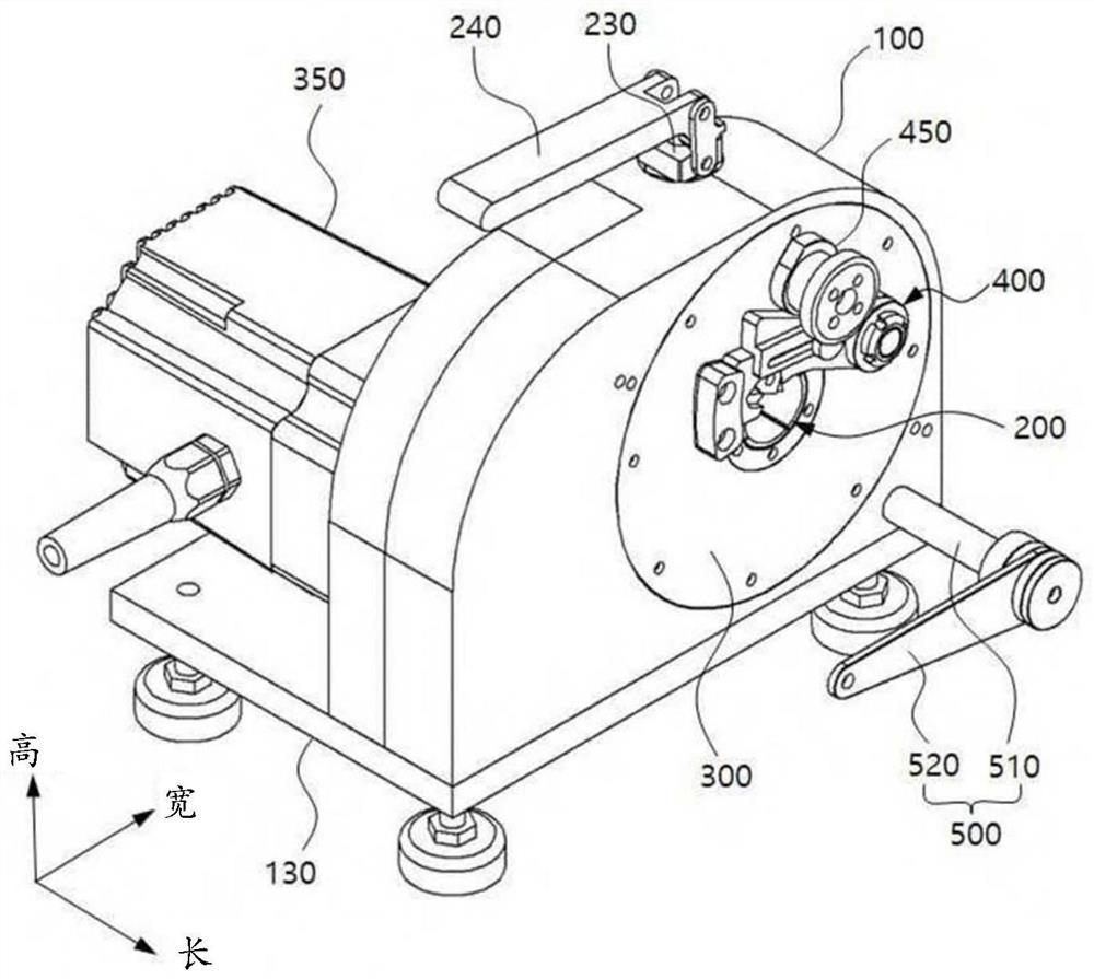
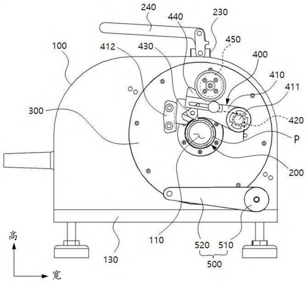
[0041] Figure 2-Figure 4 are an assembled perspective view, a right side view, and a front sectional view showing a pipe cutting device according to an embodiment of the present invention; Figure 5 It is a diagram showing the working structure of a cutting unit that rotates about the central axis of the pipe and a cutting tip that advances and retreats from the cutting unit to the center of the pipe in the pipe cutting device according to an embodiment of the present invention.

[0042] As shown in the figure, a pipe cutting device according to an embodiment of the present invention mainly includes a body 100 , a pipe fixing part 200 , a rotating disk 300 , a cam 450 and a cutting part 400 . Furthermore, the pipe cutting device of the present invention may further include a first drive unit and a second drive unit. ...


PUM


Abstract

A pipe cutting device comprises a body, a pipe fixing part, a rotating disc, a cam and a cutting part. A tube fixing portion disposed adjacent to the hollow hole and capable of fixing a tube; a rotating disk coupled to the body so as to be rotatable about the central axis of the hollow hole, and connected to a first driving unit such that the rotating disk is controlled to rotate; a cam coupled to the rotating disk so as to be rotatable about a rotation axis at a point spaced apart from the central axis, rotating together with the rotating disk, and connected to a second drive unit so that the cam is rotationally controlled; a cutting part coupled to the rotating disk so as to rotate together with the rotating disk, and in contact with the cam, so that a cutting tip advances or retreats in the direction of the center shaft according to the rotation of the cam; the pipe cutting device can minimize the deformation of the pipe to be cut, does not need to perform additional surface processing on the cutting surface of the pipe, and can automatically cut the pipe.

Description

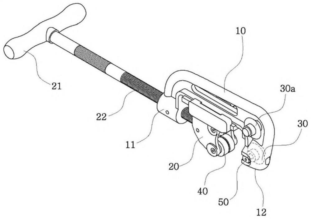
technical field [0001] The present invention relates to a pipe cutting device. After the pipe to be cut is bitten to a fixing part for fixing, the cutting part cuts the pipe by rotating around the pipe. Background technique [0002] Typically, a hacksaw or pipe cutter, etc. is used to cut the pipe. [0003] The hacksaw cuts the pipe with a saw-like cutter, and the cut surface of the pipe cut in this way is rough and has many burrs on the inner and outer peripheral edges of the cut surface. [0004] Such as figure 1 As shown, the pipe cutting machine uses a circular cutter 30 and a roller 40 to compress and cut the pipe. Since the pipe is cut by repeatedly pressing the pipe and rotating the pipe cutting machine, the cutting surface will be deformed, and the cut part will have a small internal cavity. The shrinkage results in a reduction in the outer diameter, and therefore, the cut face requires additional facing work for welding and the like. Moreover, due to the use of c...

Claims


Application Information

Patent Timeline
Patent Type & Authority Applications(China)
IPC IPC(8): B23D21/00B23D33/02
CPCB23D21/00B23D33/02B23D21/04B23B5/165B23D17/02B23D33/04B26D1/42B26D3/16B26D7/01B26D7/2628B26D2007/013
Inventor 崔仁诚
Owner DCSENG CO LTD
Learn More