An automatic laser cutting device for pipe processing that is convenient for clamping and positioning

A clamping positioning and laser cutting technology, applied in metal processing, auxiliary devices, laser welding equipment, etc., can solve the problems of inconvenient clamping and positioning of pipe fittings, poor cutting quality, pollution of smoke and dust, etc., to improve operation convenience, The effect of improving efficiency and avoiding pollution

Active Publication Date: 2022-07-12
徐州市富昌制药机械有限公司
View PDF0 Cites 0 Cited by
  • Summary
  • Abstract
  • Description
  • Claims
  • Application Information

AI Technical Summary

Problems solved by technology

[0007] The object of the present invention is to provide an automatic laser cutting device for pipe fitting processing that is convenient for clamping and positioning, so as to solve the problem that the existing laser cutting device is not convenient for clamping and positioning the pipe fittings and the cutting quality is poor and the processing is proposed in the background art. The problem of low efficiency and the emission of smoke and dust pollutes the environment

Method used


Image

  • An automatic laser cutting device for pipe processing that is convenient for clamping and positioning
  • An automatic laser cutting device for pipe processing that is convenient for clamping and positioning
  • An automatic laser cutting device for pipe processing that is convenient for clamping and positioning

Examples


Embodiment Construction

[0048] The technical solutions in the embodiments of the present invention will be clearly and completely described below with reference to the accompanying drawings in the embodiments of the present invention. Obviously, the described embodiments are only a part of the embodiments of the present invention, rather than all the embodiments. Based on the embodiments of the present invention, all other embodiments obtained by those of ordinary skill in the art without creative efforts shall fall within the protection scope of the present invention.

[0049] see Figure 1-Figure 12 , the present invention provides a kind of technical scheme:

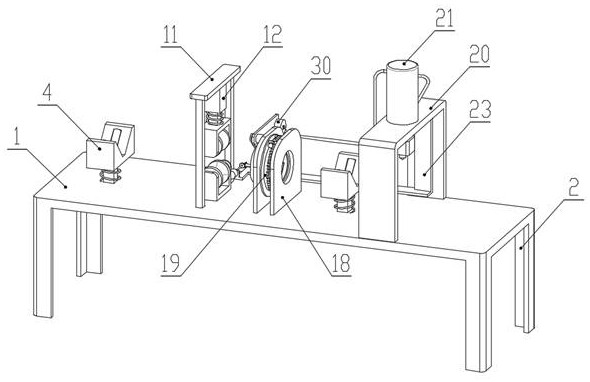
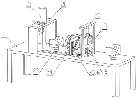
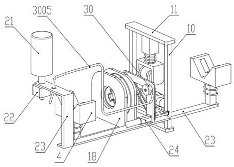
[0050] An automatic laser cutting device for pipe processing that is convenient for clamping and positioning, comprising a cutting platform 1:

[0051] Support legs 2 are fixedly connected around the lower end surface of the cutting platform 1, and telescopic columns 3 are slidably connected to the left and right sides of the upper end surf...


PUM


Abstract

The invention discloses an automatic laser cutting device for pipe processing which is convenient for clamping and positioning. A telescopic column is slidably connected, a support block is fixedly connected to the upper end surface of the telescopic column, a return spring is connected to the side surface of the telescopic column, and a first roller column is connected to the inner two sides of the support block through a shaft. The invention can facilitate the quick and convenient clamping and positioning of the pipe fittings, thereby effectively improving the operation convenience of the laser cutting device, and facilitating the automatic rotary cutting of the pipe fittings, thereby improving the cutting quality of the pipe fittings, and facilitating the cutting of the pipe fittings. The pipe fittings are automatically transported, thereby improving the cutting efficiency of the pipe fittings, and it is convenient to spray water to cool the pipe fittings to remove smoke and dust, so as to avoid environmental pollution.

Description

technical field [0001] The invention relates to the technical field of laser cutting, in particular to an automatic laser cutting device for pipe fitting processing which is convenient for clamping and positioning. Background technique [0002] The laser cutting device is to focus the laser emitted from the laser into a laser beam with high power density through the optical path system. The laser beam is irradiated on the surface of the workpiece to make the workpiece reach the melting point or boiling point. At the same time, the high-pressure gas coaxial with the beam will melt or vaporize. The metal is blown away, so that the material forms a slit, so as to achieve the purpose of cutting. Laser cutting can be used in the cutting process of the pipe to cut the pipe to the required length, but the existing laser cutting device still has the following shortcomings: [0003] 1. The pipe fittings need to be clamped and positioned before the cutting process. The operation steps...

Claims


Application Information

Patent Timeline
Patent Type & Authority Patents(China)
IPC IPC(8): B23K26/38B23K26/70B23K37/053B23K26/146B23K26/08B23K101/06
CPCB23K26/38B23K26/702B23K37/053B23K26/146B23K26/0869B23K2101/06Y02P70/10
Inventor 赵友志张松
Owner 徐州市富昌制药机械有限公司
Why Eureka
Try Eureka