Metal plate surface grinding and cutting integrated device

A metal sheet, integrated technology, applied in shearing devices, metal processing equipment, metal processing machinery parts, etc., can solve the problems of easy splashing of cooling water, low processing efficiency, pollution of the working environment, etc., to achieve good cooling effect and avoid pollution. , easy to use effect

Inactive Publication Date: 2022-05-13
宿迁搏威再生资源有限公司
View PDF0 Cites 1 Cited by
  • Summary
  • Abstract
  • Description
  • Claims
  • Application Information

AI Technical Summary

Problems solved by technology

[0004] Aiming at the deficiencies of the prior art, the present invention provides an integrated device for grinding and cutting the surface of metal sheets, which solves the problem that the cutting devices commonly used in sheet metals usually leave burrs on the back of the sheet after the cutting is completed, and two steps are required. The processing efficiency is low, and the cooling water is easy to splash when the cutting knife is used, polluting the working environment

Method used


Image

  • Metal plate surface grinding and cutting integrated device
  • Metal plate surface grinding and cutting integrated device
  • Metal plate surface grinding and cutting integrated device

Examples


Embodiment 1

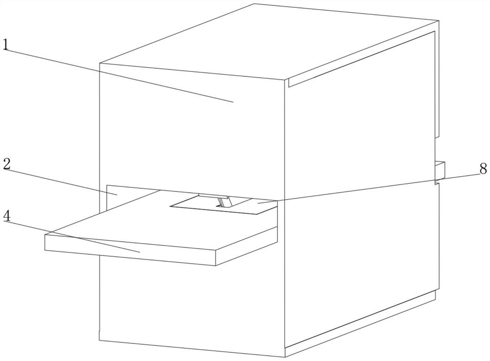
[0040] see Figure 1-Figure 3 , the present invention provides a technical solution: a metal plate surface grinding and cutting integrated device, specifically comprising:

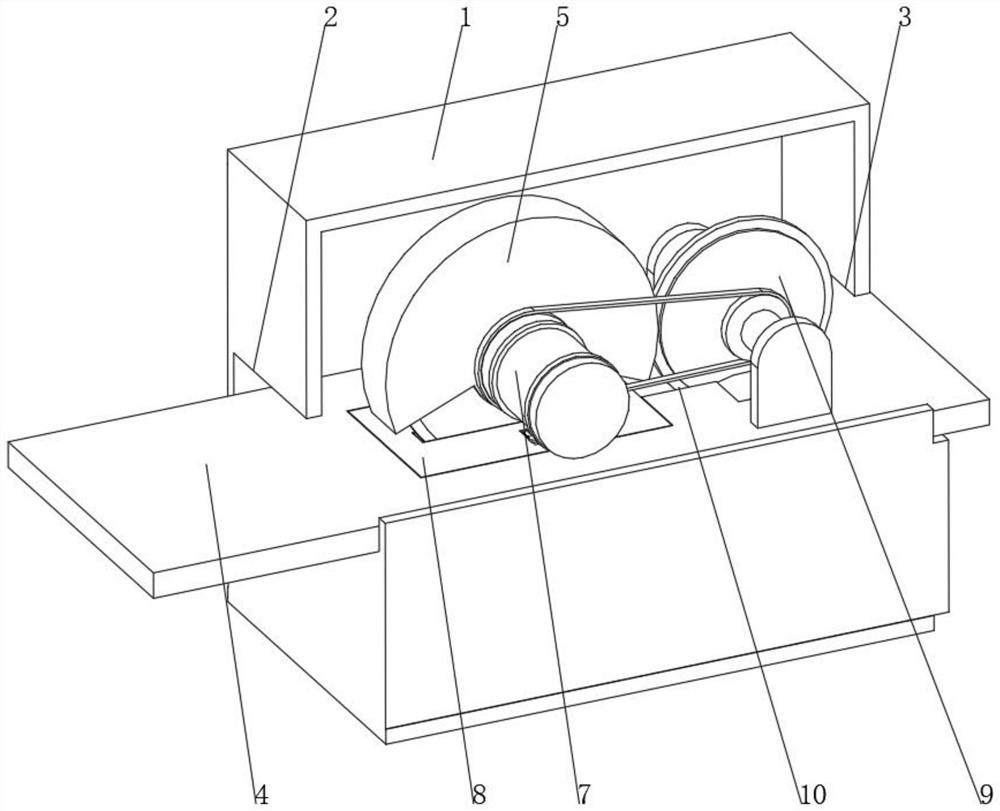
[0041] The device shell 1, the two sides of the device shell 1 are respectively provided with a material inlet 2 and a material outlet 3, and the inside of the device shell 1 is fixedly connected with a workbench 4, and the workbench 4 is provided with a cutting port 10;

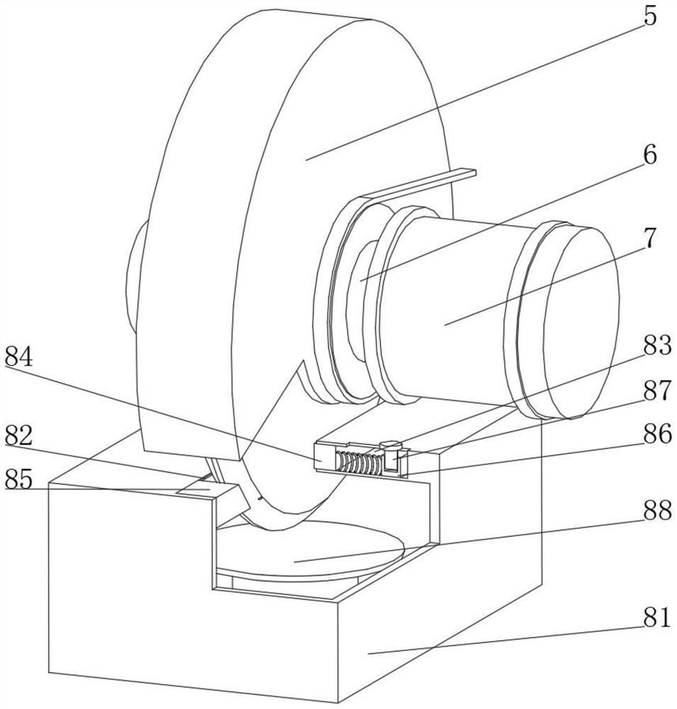
[0042] A cutting knife 5, the side of the cutting knife 5 runs through and is fixedly connected with a cutting shaft 6, one end of the cutting shaft 6 is fixedly connected with a drive motor 7, and the cutting shaft 6 is away from the drive motor 7 and is connected to the inner wall of the device shell 1 for rotation;

[0043] Cooling device 8, this cooling device 8 is arranged on the part below the cutting knife 5 on the workbench 4, the bottom of the cutting knife 5 runs through the cooling device 8 and extends to the inside of the coo...

Embodiment 2

[0052] see Figure 1-Figure 4 On the basis of Embodiment 1, the present invention provides a technical solution: the control device 88 includes a control sleeve 881, the top of the inner wall of the control sleeve 881 penetrates and is slidably connected with a sliding sleeve 882, and the top of the sliding sleeve 882 is fixedly connected with a floating Plate 883, a limit spring 884 is arranged between the bottom of the sliding sleeve 882 and the top of the inner wall of the control sleeve 881, the bottom of the inner wall of the control sleeve 881 is fixedly connected with a control switch 885, and the inner wall of the sliding sleeve 882 is slidably connected with an extrusion piston 886. The bottom of the pressure piston 886 extends to the outside of the sliding sleeve 882 and faces the control switch 885. The control sleeve 881 is arranged inside the cooling box 81 and is fixedly connected to the bottom of the inner wall of the cooling box 81. The control switch 885 is ele...

Embodiment 3

[0054] see Figure 1-Figure 5 On the basis of Embodiment 1 and Embodiment 2, the present invention provides a technical solution: the grinding device 9 includes an upper bracket 91, the inner wall of the upper bracket 91 is connected with an upper grinding disc 92 through an upper rotating shaft 96, and the outer side of the upper grinding disc 92 is covered An outer ring gear 93 is set and fixedly connected, the bottom of the outer ring gear 93 is meshed with a lower gear 94, both sides of the lower gear 94 are fixedly connected with a lower grinding disc 95 through a lower rotating shaft 97, and the bottom of the upper rotating shaft 96 is connected elastically through a rotating sleeve. Expansion plate 98, the bottom of elastic expansion plate 98 is rotatably connected with rollers, the side of elastic expansion plate 98 is fixedly connected with upper support 91, the bottom of lower rotating shaft 97 is rotatably connected with lower support 99, lower support 99 is fixedly ...


PUM


Abstract

The invention discloses a metal plate surface grinding and cutting integrated device which specifically comprises a device shell, a feeding port and a discharging port are formed in the two sides of the device shell correspondingly, a workbench is fixedly connected to the interior of the device shell, and a cutting port is formed in the workbench; the side face of the cutting knife penetrates through and is fixedly connected with a cutting rotating shaft, one end of the cutting rotating shaft is fixedly connected with a driving motor, and the end, away from the driving motor, of the cutting rotating shaft is rotationally connected with the inner wall of the device shell; and the cooling device is arranged on the portion, located below the cutting knife, of the workbench, and the bottom of the cutting knife penetrates through the cooling device and extends into the cooling device. According to the metal plate surface grinding and cutting integrated device, cooling water can be prevented from being thrown out from one side of the cutting knife and polluting the working environment, grinding can be conducted immediately after cutting is completed, plates do not need to be transferred, and the machining efficiency is high.

Description

technical field [0001] The invention relates to the technical field of sheet metal processing, in particular to an integrated device for grinding and cutting the surface of sheet metal. Background technique [0002] With the development of the modern mechanical processing industry, the requirements for cutting quality and precision are constantly improving, and the requirements for improving production efficiency, reducing production costs, and highly intelligent automatic cutting functions are also increasing. The development of CNC cutting machines must be To meet the requirements of the development of modern mechanical processing industry, cutting machines are divided into flame cutting machines, plasma cutting machines, laser cutting machines, water cutting, etc. Laser cutting machines have the fastest efficiency, highest cutting precision, and generally small cutting thickness. The cutting speed is also very fast, and the cutting surface has a certain slope. The flame c...

Claims


Application Information

Patent Timeline
Patent Type & Authority Applications(China)
IPC IPC(8): B23P23/04B23D19/00B23Q11/10B23Q11/02B24B9/04B24B41/06
CPCB23P23/04B23D19/00B23Q11/10B23Q11/02B24B9/04B24B41/068
Inventor 徐雷
Owner 宿迁搏威再生资源有限公司
Why Eureka
Try Eureka