Derrick type elevator

A technology of elevators and derricks, applied in the direction of elevators, elevators, buildings, etc. in buildings

Pending Publication Date: 2022-05-13
佛山市和众电梯技术有限公司
View PDF0 Cites 0 Cited by
  • Summary
  • Abstract
  • Description
  • Claims
  • Application Information

AI Technical Summary

Problems solved by technology

[0003] In order to overcome the defects in the prior art, the present invention provides a derrick elevator to solve the above and related problems

Method used


Image

  • Derrick type elevator
  • Derrick type elevator
  • Derrick type elevator

Examples


Embodiment 1

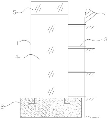
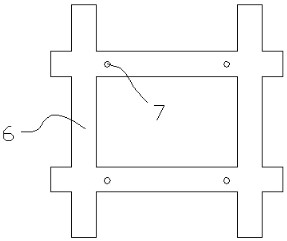
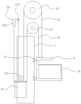
[0038] combine Figure 1 to Figure 7 The derrick type elevator shown includes a hoistway frame 1 arranged on one side of the floor wall, the upper end of the hoistway frame 1 is provided with a machine room 5, and a part of the decorative plate 4 is arranged on the outside of the hoistway frame 1. The decorative plate 4. Glass plates can be used. The lower end of the hoistway frame 1 is installed on the concrete foundation 2. The concrete foundation 2 is a well-shaped structure 6. A car module is installed in the hoistway frame 1. The car module includes a A guide rail assembly on one side of the hoistway frame 1, a counterweight 10 is slidably installed in the guide rail assembly, a car assembly is slidably installed on one side of the guide rail assembly, and a power output motor 12 is installed in the machine room 5. The top of the power output motor 12 is provided with a speed-limited stop device 13, the output shaft on the power output motor 12 is equipped with a power gear...

Embodiment 2

[0049] Such as Figure 8 As shown, the difference between the second embodiment and the first embodiment is that the second synchronous belt connection buffer seat 15 is respectively installed on the sliding frame 29, and the second synchronous belt connection buffer seat 15 and the synchronous belt 19 The ends are connected, and the side of the second synchronous belt connected to the buffer seat 15 is provided with a second wire rope fixing port 17, and the second wire rope fixing port 17 is connected to the end of the steel wire rope 18; The seat 15 and the second wire rope fixing port 17 directly connect the synchronous belt 19 and the wire rope 18 with the balance weight 10, and form a 1:1 suspension ratio with the car body, so that the structure is more simplified and compact, and the transmission efficiency is higher.

[0050] The structure of the second synchronous belt connection buffer seat 15 is the same as that of the first synchronous belt connection buffer seat 1...

Embodiment 3

[0052] Such as Figure 9 with Figure 10 As shown, the difference between the third embodiment and the first embodiment is that the side of the well-shaped frame 6 close to the floor wall is flat when viewed from the side, so that the distance between the hoistway frame 1 and the floor wall is Smaller, there is no need to install the corridor attachment 3 between the hoistway frame 1 and the floor wall.


PUM


Abstract

The invention relates to the technical field of elevators, and discloses a derrick type elevator which comprises a well frame arranged on one side of a floor wall, a machine room is arranged at the upper end of the well frame, a decorative plate is arranged on the outer side of the well frame, the lower end of the well frame is installed on a concrete foundation, and the concrete foundation is of a #-shaped framework. A lift car module is installed in the shaft frame, the lift car module comprises a guide rail assembly installed on one side in the shaft frame, a balance weight is installed in the guide rail assembly in a sliding mode, and a lift car assembly is installed on one side of the guide rail assembly in a sliding mode; the derrick type elevator is high in transmission efficiency, the occupied hoistway area is correspondingly reduced, the cost is relatively reduced, environmental pollution and carbon emission are reduced, the derrick type elevator is suitable for additionally installing elevators, open-air elevators and household elevators in old buildings, stability of the hoistway frame can be ensured when the elevators run, settlement of the buildings and other environmental factors can be prevented, and the safety of the elevators is improved. And related safety problems of the elevator or the user building are caused.

Description

technical field [0001] The invention relates to the technical field of elevators, in particular to a derrick elevator. Background technique [0002] Usually, traction elevators are used in conjunction with steel structure shafts to install elevators in old buildings, and combined derricks are further used; for home elevators, hydraulic elevators and screw drive elevators are specially used for matching due to the small shafts. These elevators all have their own deficiencies, such as the former having shortcomings such as high cost and environmental pollution, and the latter having defects such as too low mechanical transmission efficiency and too low operating speed. In addition, for outdoor elevators, only escalators have this function, and its similar elevator technology only appears in foreign countries. Contents of the invention [0003] In order to overcome the defects in the prior art, the present invention provides a derrick elevator to solve the above and related ...

Claims


Application Information

Patent Timeline
Patent Type & Authority Applications(China)
IPC IPC(8): B66B9/00B66B7/06B66B7/02B66B11/02B66B11/00E04F17/00B66B7/08
CPCB66B9/00B66B7/06B66B7/02B66B11/0206B66B11/00E04F17/005B66B7/08
Inventor 吴哲
Owner 佛山市和众电梯技术有限公司
Why Eureka
Try Eureka