New energy air purification equipment

A kind of air purification equipment and new energy technology, applied in the field of air purification, can solve the problems of short residence time, inconvenient cleaning and removal of debris and dust inside the purification device, and affect the health of indoor personnel, so as to improve the purification effect and facilitate disassembly and collection Dust debris, enhance the effect of sterilization and filtration

Active Publication Date: 2022-05-13
深圳市鹏跃新能源科技有限公司
View PDF10 Cites 0 Cited by
  • Summary
  • Abstract
  • Description
  • Claims
  • Application Information

AI Technical Summary

Problems solved by technology

[0003] At present, new energy air purification equipment is widely used. When the existing air purification equipment is in use, the internal filter is prone to moisture and other problems during the long-term adsorption and purification process. The humid internal environment is easy to breed mold and other substances, resulting in Purified air produces peculiar smell, which affects the use effect of the equipment. Therefore, it is necessary to clean or replace the filter device in the purification device. However, the internal filter screen of most purifiers is difficult to disassemble due to the complex structure of the device, and it is not convenient to clean the debris inside the purification device. and dust removal; the purifier inhales air from the outside and then passes through the filter before outputting. When the flow rate is too fast, the air stays in the purifier for a short time, and cannot fully contact the filter element at the temporal part and is absorbed. Filtration, resulting in poor purification effect and affecting the health of indoor personnel; most purifiers use rechargeable lithium batteries to power the suction device of the equipment, requiring frequent replacement of battery power, causing environmental pollution and waste of resources

Method used


Image

  • New energy air purification equipment
  • New energy air purification equipment
  • New energy air purification equipment

Examples


Embodiment Construction

[0032] The technical solution of the present invention will be described in further detail below in conjunction with specific embodiments and accompanying drawings:

[0033] Apparently, the described embodiments are only some of the embodiments of the present invention, but not all of them. Based on the embodiments of the present invention, all other embodiments obtained by persons of ordinary skill in the art without making creative efforts belong to the protection scope of the present invention.

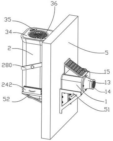
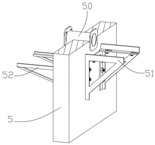
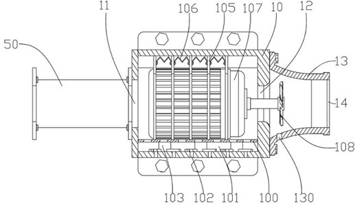
[0034] The new energy air purification equipment includes: a wall body 5, an outer support frame 51 is fixed on the outdoor side of the wall body 5, and an external body 1 is detachably fixed above the outer support frame 51, and the external body 1 includes an external shell 10, the external body 1 The casing 10 is provided with an external unit pipe hole 11 at the center of the side wall near the wall 5, and a communication pipe 50 is interspersed on the wall 5. The hole 11 is c...


PUM


Abstract

The invention discloses new energy air purification equipment which comprises a wall body, an external machine body is arranged on the outer side of the wall body, a first motor and a first rotating vane are arranged in the external machine body, metal meshes are arranged in the external machine body in an array mode, a photovoltaic panel is arranged above the external machine body, and an internal machine body is arranged on the inner side of the wall body. The inner machine body and the outer machine body are connected through a communicating pipeline, an air filter element is inserted into the inner shell in a penetrating mode, a second motor and second fan blades are arranged above the air filter element, the second motor is sleeved with an auxiliary filter sleeve, and an air outlet assembly is connected to the upper portion of the auxiliary filter sleeve in an inserted mode. According to the air purifier, the photovoltaic panel collects energy to supply power to the first motor, the first motor sucks air and enters the internal machine body through the communicating pipeline, the internal machine body purifies and decelerates the air through the air filter element and the air outlet assembly, and the purified air is exhausted into a room.

Description

technical field [0001] The invention belongs to the field of air purification, and in particular relates to a new energy air purification device. Background technique [0002] Air purifier refers to the ability to absorb, decompose or transform various pollutants in the air (generally including PM2.5, dust, pollen, odor, decoration pollution such as formaldehyde, bacteria, allergens, etc.), and effectively improve indoor air quality. Cleanliness products are used in home, office, medical, and industrial fields. The main function of the air purifier is to remove particulate matter in the air, including allergens, indoor PM2.5, etc., and it can also solve problems caused by decoration or Indoor, underground space, and volatile organic compound air pollution problems in vehicles caused by other reasons. [0003] At present, new energy air purification equipment is widely used. When the existing air purification equipment is in use, the internal filter is prone to moisture and ...

Claims


Application Information

Patent Timeline
Patent Type & Authority Applications(China)
IPC IPC(8): F24F8/10F24F8/20F24F13/28H02J7/35
CPCF24F8/10F24F8/20F24F13/28H02J7/35
Inventor 江丽娜
Owner 深圳市鹏跃新能源科技有限公司
Why Eureka
Try Eureka