Eureka AIR delivers breakthrough ideas for toughest innovation challenges, trusted by R&D personnel around the world.

Drying equipment for disinfecting medical apparatus and instruments

A technology for drying equipment and medical equipment, applied in the field of medical drying, can solve the problems of difficulty in ensuring the air quality inside the air inlet duct, speeding up the work efficiency of medical staff, shortening the sterilization distance, etc., so as to reduce drying time and labor. the effect of increasing the drying rate

Inactive Publication Date: 2022-05-13
广东大成金健康科技有限公司
View PDF4 Cites 2 Cited by
  • Summary
  • Abstract
  • Description
  • Claims
  • Application Information

AI Technical Summary

Problems solved by technology

The device for drying and disinfecting surgical medical instruments after cleaning is equipped with a first transmission device, a second transmission device, fan blades, a handle, a loading board, a box body, a net plate, a telescopic device, a slider, a turntable, and a first spring. , sliding sleeve, ultraviolet disinfection light board, traction rope, rotating shaft and bearing, so that there is no need to dry and sterilize the medical equipment separately, which not only saves time, but also speeds up the work efficiency of medical staff", the drying device is in use At the same time, the crack detection of the drying air inlet pipe was not carried out, so that after the cracks appeared inside the drying air inlet pipe, it was difficult to ensure the quality of the air inside the air inlet pipe due to the shortened sterilization distance inside the pipe, which in turn made the device Secondary pollution is prone to occur during the drying process

Method used


Image

  • Drying equipment for disinfecting medical apparatus and instruments
  • Drying equipment for disinfecting medical apparatus and instruments
  • Drying equipment for disinfecting medical apparatus and instruments

Examples


Embodiment 1

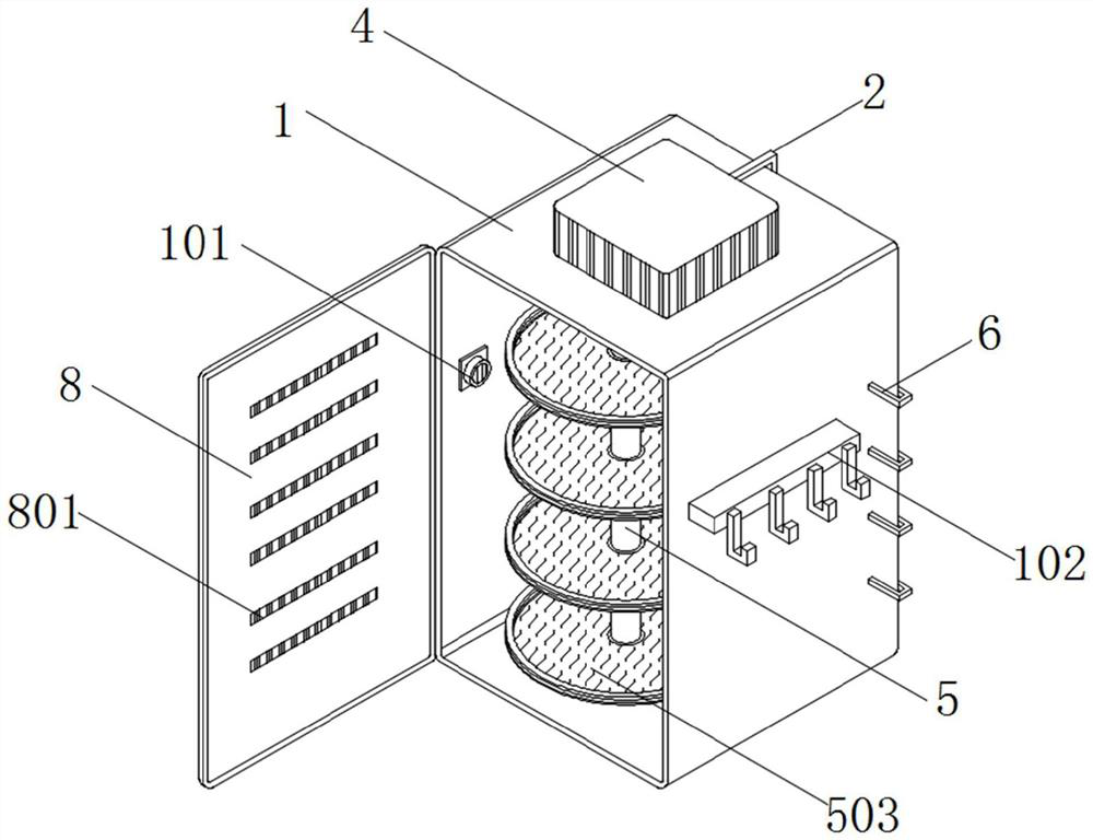
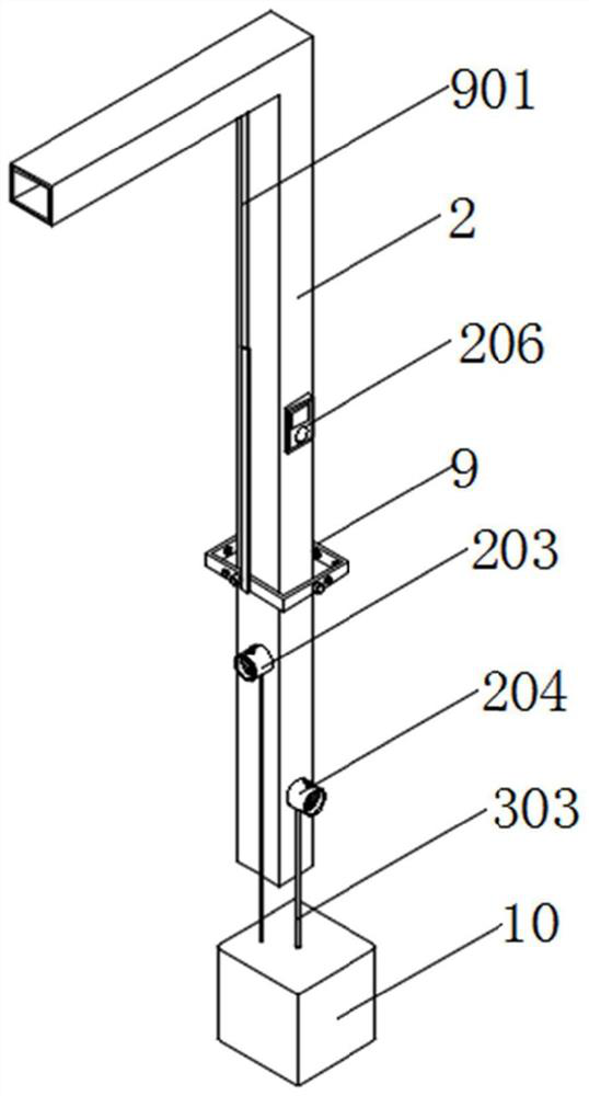
[0056] see figure 1 , figure 2 , image 3 with Figure 4 , an embodiment provided by the present invention: a drying equipment for disinfection of medical instruments, comprising a drying cabinet body 1 and a sterile air inlet pipe 2, the top of the drying cabinet body 1 is equipped with a drying adjustment box 4, an L-shaped sterile air inlet pipe 2 is installed through the back of the drying adjustment box 4;

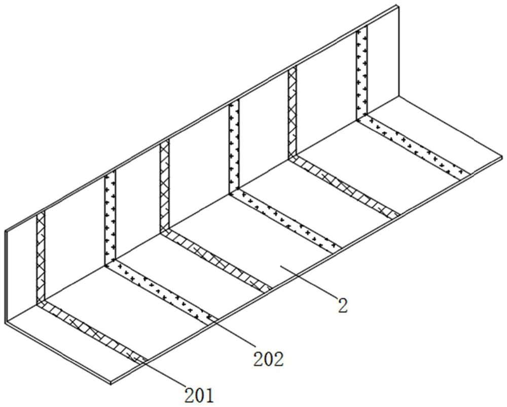
[0057] The inner wall of the sterile air inlet pipe 2 is equidistantly arranged with ultraviolet lamp circles 201 and heating mesh circles 202, and the ultraviolet lamp circles 201 and heating mesh circles 202 are arranged at intervals, and the tail end of the sterile air inlet pipe 2 is a closed structure, sterile The surface of the air inlet pipe 2 is equipped with No. 1 air inlet pipe 203 and No. 2 air inlet pipe 204 arranged up and down, and No. 1 air inlet pipe 203 and No. 2 air inlet pipe 204 are respectively in two mutually perpendicular planes. An electro...

Embodiment 2

[0067] see figure 1 , Figure 5 with Image 6 , an embodiment provided by the present invention: a drying equipment for medical device disinfection, comprising a drying cabinet body 1 and a drying adjustment box 4, a heating frame 402 is installed on the inner wall of the drying adjustment box 4, and the drying The bottom wall of the dry adjustment box 4 is installed with a regulating pipe 401, and the tail end of the regulating pipe 401 extends to the inside of the drying cabinet body 1. The inner wall of the regulating pipe 401 is equipped with a one-way valve 404, and the inner wall of the regulating pipe 401 A support frame 406 is installed, the bottom of the support frame 406 is connected with a miniature electric telescopic rod 405, the tail end of the miniature electric telescopic rod 405 is connected with a tapered air outlet pipe 403 through the support frame 406, and the inner support frame 406 of the tapered air outlet pipe 403 The size is smaller than the size of...

Embodiment 3

[0075] see figure 1 , Figure 7 with Figure 8 , an embodiment provided by the present invention: a drying equipment for medical device disinfection, comprising a drying cabinet body 1 and a support rod 5, the top wall of the drying cabinet body 1 is equipped with a support rod 5, and The length of the support rod 5 is less than the internal height of the drying cabinet cabinet 1, the surface of the support rod 5 is equipped with a drying rack 501 through the bearing sleeve, and the inside of the drying rack 501 is provided with a storage tank 502, and the inside of the storage tank 502 is embedded A semicircular net plate 503 is installed together, and a protruding strip 504 is installed on the surface of the net plate 503 , and the cross-sectional dimension of the protruding strip 504 is larger than that of the receiving groove 502 .

[0076] Specifically, after drying, in order to prevent medical personnel from manually picking up the dried medical equipment, the accepted...


PUM


Abstract

The drying equipment comprises a drying cabinet body and a sterile air inlet pipe, a drying adjusting box is installed at the top of the drying cabinet body, and the sterile air inlet pipe is installed on the back face of the drying adjusting box in a penetrating mode; an ultraviolet lamp ring and a heating net ring are arranged on the inner wall of the sterile air inlet pipe, a first air inlet pipe and a second air inlet pipe which are arranged up and down are installed on the surface of the sterile air inlet pipe, and electronic valves are installed on the surfaces of the first air inlet pipe and the second air inlet pipe; a temperature and humidity sensor is mounted on the surface, provided with the second air inlet pipe, of the sterile air inlet pipe; and a supporting rod is mounted on the top wall of the drying cabinet body. By arranging the sterile air inlet pipe, internal air has relatively sufficient movement duration so as to ensure that the internal air can be sterilized for sufficient duration in the process of entering the drying adjusting box through the sterile air inlet pipe, so that sterility of circulating air in the sterile air inlet pipe is realized.

Description

technical field [0001] The invention relates to the technical field of medical drying, in particular to a drying equipment used for disinfection of medical instruments. Background technique [0002] During the use of medical devices such as hemostatic clips and tweezers, they usually need to be cleaned, disinfected, and dried for secondary use, so as to reduce the frequency of replacement of medical consumables and reduce medical costs. During this period, it is necessary A drying device is used to assist medical personnel to dry the cleaned medical instruments for recycling and reuse. [0003] The defects of existing medical drying equipment are: [0004] 1. The patent document CN109028854A discloses a medical device drying equipment, "including a bottom plate, a support rod, a frame body, a heating wire, a clasp, an L-shaped guide rod, a screen frame, a first guide sleeve, and a first straight guide rod. , rollers, mounting bases, motors, the first rotating shaft, etc.; ...

Claims


Application Information

Patent Timeline
Patent Type & Authority Applications(China)
IPC IPC(8): F26B11/18F26B21/00F26B21/08F26B21/10F26B25/00F26B25/02A61L2/10
CPCF26B11/181F26B21/004F26B21/08F26B21/10F26B25/003F26B25/009F26B25/02A61L2/10
Inventor 陈丽丹
Owner 广东大成金健康科技有限公司
Why Eureka
Eureka Blog
Learn More