Alternating current sampling circuit of transformer area intelligent fusion terminal

An AC sampling and circuit technology, applied in the direction of circuit devices, measuring electricity, electrical components, etc., can solve the problems of data loss, low AC sampling accuracy, insufficient power supply, etc., and achieve the effect of improving sampling accuracy

Pending Publication Date: 2022-05-13
ZHEJIANG WELLSUN INTELLIGENT TECH CO LTD
0 Cites 0 Cited by

AI-Extracted Technical Summary

Problems solved by technology

[0004] The purpose of the present invention is to provide an AC sampling circuit for an intelligent fusion terminal in a station area, aiming to solve th...

Method used

In the present embodiment, described communication electrical isolation circuit is processor, and described metering chip is three-phase electric energy metering module, and A phase current transformer, B phase current transformer and C phase current transformer are connected with three phases respectively The phase electric energy metering module is electrically connected, and the A-phase current transformer, B-phase current transformer and C-phase current transformer are respectively connected with voltage sensors, the processor is electrically connected with the three-phase electric energy metering module, and the three-phase alternating current passes through the current mutual in...

Abstract

The invention relates to the technical field of electronic measurement, in particular to an alternating current sampling circuit of a transformer area intelligent fusion terminal. Comprising a voltage signal step-down circuit, a current signal acquisition circuit, a metering chip, a communication electrical isolation circuit, an active pulse output isolation circuit and a reactive pulse output isolation circuit, the voltage signal step-down circuit converts a strong current voltage signal into a weak current voltage signal, and the current signal acquisition circuit converts a strong current current signal into a weak current current signal. The metering chip is used for converting a weak current voltage signal and a weak current signal into a digital sampling signal, an active pulse signal and a reactive pulse signal respectively, the communication electrical isolation circuit outputs the digital sampling signal, the active pulse output isolation circuit outputs the active pulse signal, and the reactive pulse output isolation circuit outputs the reactive pulse signal. Through the above structure, the sampling precision is improved, and stable operation can be realized by using a standby power supply after power failure.

Application Domain

Technology Topic

Image

  • Alternating current sampling circuit of transformer area intelligent fusion terminal
  • Alternating current sampling circuit of transformer area intelligent fusion terminal
  • Alternating current sampling circuit of transformer area intelligent fusion terminal

Examples

  • Experimental program(1)

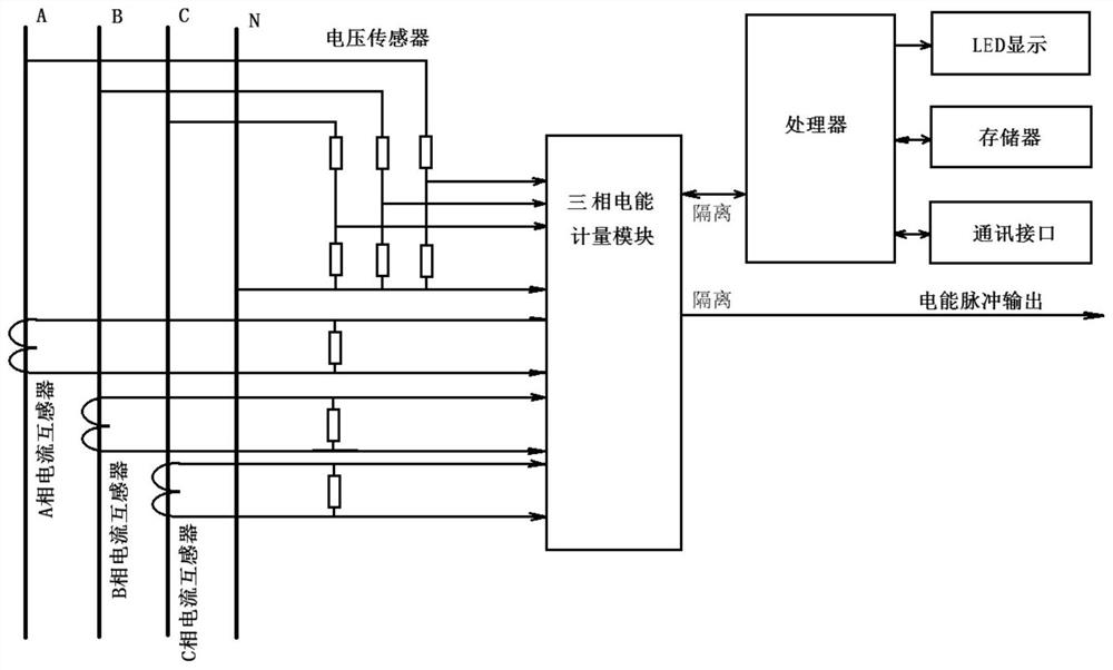
Example Embodiment

[0021] Embodiments of the present invention are described in detail below, examples of the embodiments are shown in the drawings, wherein the same or similar designations from beginning to end indicate the same or similar elements or elements with the same or similar functions. The embodiments described below by reference to the accompanying drawings are exemplary and are intended to be used to explain the present invention, and cannot be construed as a limitation of the present invention.
[0022] In the description of the present invention, it is to be understood that the term "length", "width", "up", "down", "front", "back", "left", "right", "vertical", "horizontal", "top", "bottom", "inside", "outside" and other indications of the orientation or position relationship is based on the orientation or position relationship shown in the drawings, only to facilitate the description of the present invention and simplify the description, and not to indicate or imply that the means or elements referred to must have a specific orientation, structured and operated in a particular orientation, It can therefore not be construed as a limitation of the present invention. Further, in the description of the present invention, "multiple" means two or more, unless otherwise expressly specifically qualified.
[0023] See Figures 1 through 7 , the present invention provides an AC sampling circuit of the intelligent fusion terminal in the Taiwan area, the AC sampling circuit of the intelligent fusion terminal in the Taiwan area comprises a voltage signal step-down circuit, a current signal acquisition circuit, a metering chip, a communication galvanic isolation circuit, an active pulse output isolation circuit and a reactive pulse output isolation circuit, the voltage signal step-down circuit converts a strong current voltage signal into a weak current signal, and input to the metering chip, the current signal acquisition circuit converts the strong current signal into a weak current signal, And input to the metering chip, the measurement chip is used to convert the weak current voltage signal and the weak current signal into a digital sampling signal, an active pulse signal and an reactive pulse signal, the communication galvanic isolation circuit will be a digital sampling signal output, the active pulse output isolation circuit will be an active pulse signal output, the reactive pulse output isolation circuit will be reactive pulse signal output.
[0024] In the present embodiment, the communication galvanic isolation circuit is a processor, the metering chip is a three-phase energy measurement module, A-phase current transformer, B-phase current transformer and C-phase current transformer are electrically connected to the three-phase energy measurement module, and the A-phase current transformer, B-phase current transformer and C-phase current transformer are respectively connected to a voltage sensor, the processor is electrically connected to the three-phase energy metering module, and the three-phase AC current transformer and step-down resistor are converted into weak current AC signals, Then through the three-phase energy measurement module to obtain voltage and current digital sampling signal, active energy signal, active pulse and reactive pulse, the final digital sampling signal and active energy signal through the communication galvanic isolation circuit output to the processor, active pulse and reactive pulse through the active pulse output isolation circuit and the reactive pulse output isolation circuit output to the pulse output circuit, to achieve improved sampling accuracy, after power failure using a backup power supply can be stable operation.
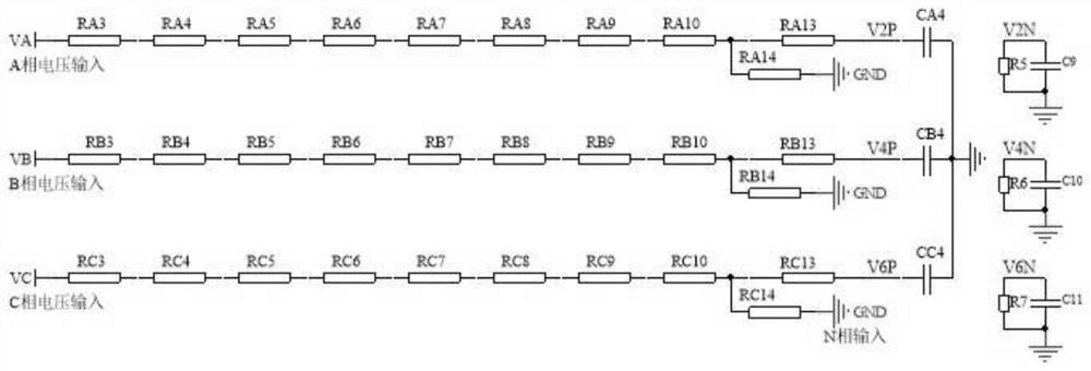
[0025] Further, the voltage signal buck circuit comprises a plurality of buck resistors and filter circuits, each two adjacent between the step-down resistors are in series, the strong voltage signal input to a plurality of the step-down resistor, a plurality of step-down resistors will be a strong voltage signal after step-down input to the filter circuit, and input the metering chip.
[0026] In the present embodiment, taking the A phase voltage as an example, the A phase voltage VA input is composed of resistance RA3, resistance RA4, resistance RA5, resistance RA6, resistance RA7, resistance RA8, resistance RA9, resistance RA10 in series of step-down resistors, the step-down resistor converts the strong voltage signal into a weak current voltage signal, and then inputs the filter circuit composed of resistance RA13, resistance RA14 and capacitor CA4, and finally the filtered A phase weak current voltage signal is input into the metering chip, The buck circuit of the B phase and C phase voltage signals is the same structure as the A phase buck circuit structure, the B phase and C phase weak current voltage signals are input into the metering chip.
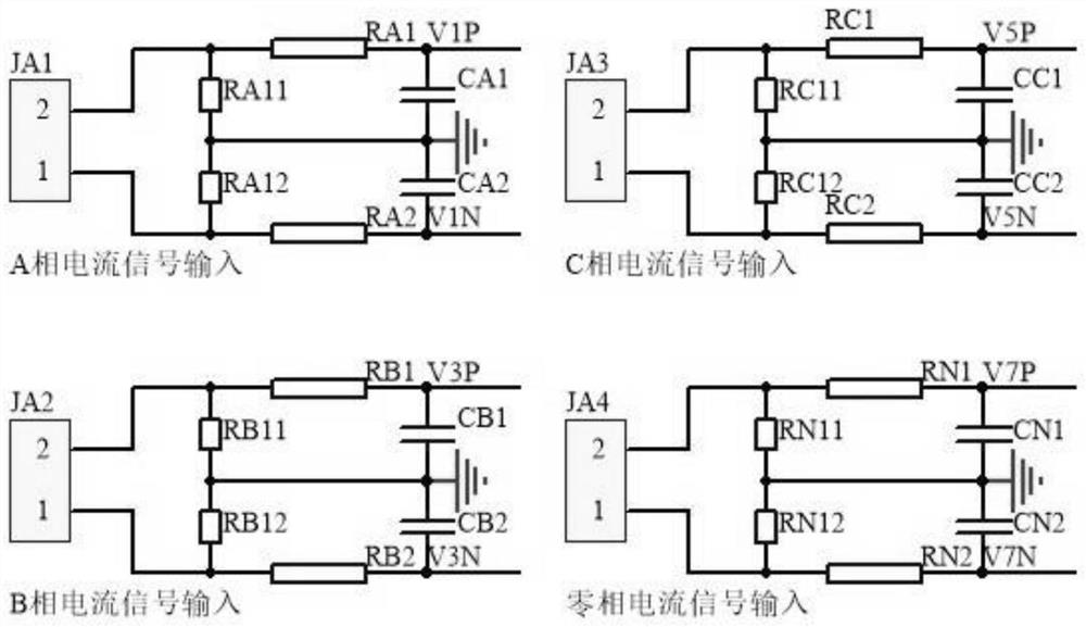
[0027] Further, the current signal acquisition circuit comprises a current transformer and a differential circuit, a strong current signal through the current transformer after generating a weak current current signal, and input to the differential circuit, and finally input the metering chip, the differential circuit for eliminating the error when collecting the current signal.
[0028] In the present embodiment, taking the A phase current as an example, the differential circuit comprises a resistor RA11, resistance RA1, resistance RA12, resistance RA2 and capacitor CA1, capacitor CA2, A phase strong current signal input current transformer JA1, current transformer JA1 converts a strong current signal into a weak current signal, the weak current signal through the resistance RA11, resistance RA1, resistance RA12, resistance RA2 and capacitor CA1, capacitor CA2, input to the metering chip, B phase The downcurrent circuit of the C phase and zero phase current signals is the same structure as the A phase down current circuit, and the B phase and C phase weak current signals are input into the metering chip.
[0029] Further, the metering chip is provided with a digital-to-analog conversion unit, a digital multiplier, an active energy calculation unit, an active energy metering unit, an energy pulse generator and a frequency divider, the digital-to-analog conversion unit will be a weak voltage signal and a weak current signal for digital-to-analog conversion, to obtain a digital sampling signal of voltage and current, the digital sampling signal is input to the digital multiplier to obtain an active power signal, the active power signal is input to the active power calculation unit to obtain an active energy signal, The active energy signal is input to the energy pulse generator and the active energy measurement unit, the active energy signal generates an active energy pulse and an active energy pulse under the action of the energy pulse generator and the frequency divider; the metering chip also has a filter and a phase correction unit, the digital sampling signal of voltage and current is corrected by the filter and the phase correction unit, the corrected digital sampling signal is input into the digital multiplier to obtain an active power signal.
[0030] In the present embodiment, the metering chip in operation, the weak current signal and the weak current voltage signal through the digital analog into a digital sampling signal, the digital sampling signal through the filter and the phase correction unit for filtering and phase correction, the corrected digital sampling signal is input to the digital multiplier and the active energy calculation unit for calculation, and obtain an active energy signal, the active energy signal is input to the meter of the active energy measurement unit and the energy pulse generator, Active energy signal generates an active pulse and reactive pulse under the action of the energy pulse generator and the frequency divider, a digital sampling signal, an active energy signal, an active pulse and an reactive pulse output to the communication galvanic isolation circuit, the active pulse output isolation circuit and the reactive pulse output isolation circuit.
[0031] Further, the communication galvanic isolation circuit comprises a reset isolation optocoupler and management chip, the management chip transmits a reset signal to the metering chip via the reset isolation optocoupler; the communication galvanic isolation circuit further comprises a digital isolator, the metering chip communicates with the management chip through the digital isolator, the digital isolator for the measurement chip and the management chip electrically isolated.
[0032] In the present embodiment, the communication galvanic isolation circuit in operation, the management chip via optocoupler Om1 to the metering chip to transmit a reset signal, the metering chip and the management chip through the digital isolator Ud1 communication, when the power supply is powered down, the digital isolator Ud1 will be the metering chip and the management chip between the communication disconnected, standby power consumption reduced, the management chip may operate stably.
[0033] Further, the active pulse output isolation circuit comprises an active pulse isolation optocoupler and an active pulse output circuit, the active pulse isolation optocoupler input terminal is connected to the active pulse signal transmitted by the metering chip, the active pulse isolation optocoupler output terminal is connected to the base electrode of the active pulse output circuit, and outputs an active pulse signal at the collector; the reactive pulse output isolation circuit comprises the reactive pulse isolation optocoupler and reactive pulse output circuit, The reactive pulse isolation optocoupler input terminal is connected to the reactive pulse signal transmitted by the metering chip, the reactive pulse isolation optocoupler output terminal is connected to the base electrode of the reactive pulse output circuit in the triode, and the reactive pulse signal is output at the collector.
[0034] In the present embodiment, taking the active pulse as an example, the active pulse P_Pulse is high, the optocoupler Om5 conduction makes the B-pole potential of the triode Q3 pull low, the triode Q3 is in the cut-off state, the C pole potential is pulled high, the active pulse signal CF1 output is high, the active pulse P_Pulse is low, the optocoupler cut-off makes the B-pole potential of the triode Q3 pulled high, the triode Q3 is in the on state, the C pole potential is pulled low, the active pulse signal CF1 output is low, and the active pulse P_ Pulse potential and active pulse signal CF1 is the same potential, active pulse P_Pulse through the optocoupler Om5 isolation output active pulse signal CF1, the reactive pulse output isolation circuit is similar to the active pulse output isolation circuit, reactive pulse Q_Pulse is high, photocoupler Om6 conduction so that the B pole potential of the triode Q4 is pulled low, the triode Q4 is in the cut-off state, the C pole potential is pulled up, the reactive pulse signal CF2 output high level, reactive pulse Q_ When Pulse is low, the optocoupler cutoff makes the B-pole potential of the triode Q4 high, the triode Q4 is in the on state, the C-pole potential is pulled low, the reactive pulse signal CF2 outputs low, the reactive pulse Q_Pulse the potential is the same as the reactive pulse signal CF2, and the reactive pulse Q_Pulse isolated through the optocoupler Om6 to output the reactive pulse signal CF2.
[0035] The above disclosure is only a preferred embodiment of the present invention only, of course, can not be used to limit the scope of rights of the present invention, those of ordinary skill in the art can understand all or part of the process of implementing the above embodiments, and in accordance with the claims of the present invention to make equivalent changes, still belongs to the scope of the invention.

PUM

no PUM

Description & Claims & Application Information

We can also present the details of the Description, Claims and Application information to help users get a comprehensive understanding of the technical details of the patent, such as background art, summary of invention, brief description of drawings, description of embodiments, and other original content. On the other hand, users can also determine the specific scope of protection of the technology through the list of claims; as well as understand the changes in the life cycle of the technology with the presentation of the patent timeline. Login to view more.

Similar technology patents

Analog accelerometer output signal transmission device

InactiveCN103389091AImprove sampling accuracySolve the problem of easy introduction of electromagnetic interference signalsNavigation by speed/acceleration measurementsVIT signalsEngineering
Owner:西安应用光学研究所

Method and apparatus for identifying high-risk commodities by sampling inspection

InactiveCN109146585AReduce sampling costImprove sampling accuracyBuying/selling/leasing transactionsLimit valueComputer science
Owner:BEIJING JINGDONG SHANGKE INFORMATION TECH CO LTD +1

Classification and recommendation of technical efficacy words

Why Eureka
Try Eureka