Winding needle driving device, winding head and winding machine

A driving device and winding head technology, applied in the direction of sustainable manufacturing/processing, climate sustainability, final product manufacturing, etc., can solve the problems of large moment of inertia of the reel, low production efficiency, low motor power, etc., and achieve responsive The effect of fast speed, lower quality and higher speed

Pending Publication Date: 2022-05-13
三一技术装备有限公司
View PDF8 Cites 0 Cited by
  • Summary
  • Abstract
  • Description
  • Claims
  • Application Information

AI Technical Summary

Problems solved by technology

[0003] Therefore, the technical problem to be solved by the present invention is to overcome the defects of large reel moment of inertia, small motor power and low production efficiency in the prior art, thereby providing a winding needle driving device, winding head and winding machine

Method used


Image

  • Winding needle driving device, winding head and winding machine
  • Winding needle driving device, winding head and winding machine
  • Winding needle driving device, winding head and winding machine

Examples


Embodiment 1

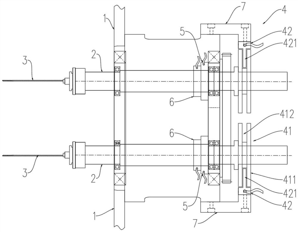
[0049] Reference Figure 1 and Figure 2 , a needle reel drive device, including needle reel shaft 2 and magnetic drive mechanism 4. Wherein, the needle reel 2 can be switched sequentially between multiple stations; the magnetic drive mechanism 4 is located at one end of the needle reel 2, the magnetic drive mechanism 4 includes rotor 41 and a plurality of stators 42, the rotor 41 is fixed with the needle reel 2 fixed, the stator 42 and the station one-to-one corresponding to the frame of the needle reel drive device, the stator on either station is suitable for connection with the rotor drive, for driving the needle reel 2 rotation.

[0050] Using the technical scheme of the present invention, the needle reel 2 is provided on the rotor 41 and stator 42, by the magnetic drive mechanism 4 to drive the rotation of the needle reel 2, the magnetic drive mechanism 4 in the stator 42 fixed on the frame of the reel drive device, to achieve the needle reel 2 drive device from the reel 1 de...

Embodiment 2

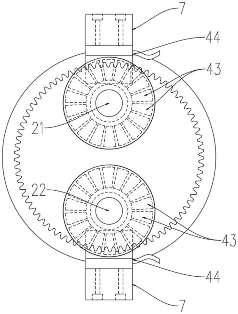
[0063] The present embodiment provides a second embodiment of the magnetic drive mechanism 4. Reference Figure 3 , the difference with Example 1 is that one end of the needle reel 2 is provided side by side with three turntable bodies 411, each turntable body 411 is opened with a ring groove to form a docking gap 412. Three side-by-side turntable bodies 411 constitute three docking clearances 412. Correspondingly, the stator 42 and three insertion gaps 412 one-to-one corresponding to the setting of three inserts 421, the shape of the insert 421 is not limited, in the present embodiment, the insert 421 is a rectangular block, with reference Figure 2 。 That is, the stator 42 is disposed on one side of the turntable body 411, which corresponds only to the local permanent magnet 43 on the turntable body 411. Of course, as a deformed embodiment of the present embodiment, three parallel turntable bodies 411 may be provided in one piece, that is, a turntable body 411, along the axial jux...

Embodiment 3

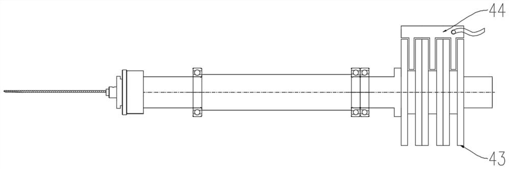
[0065] The present embodiment provides a third embodiment of the magnetic drive mechanism 4. Reference Figure 4 , the difference from Example 1 is that the rotor 41 comprises an excitation winding 44, the stator 42 includes a permanent magnet 43. Specifically, the turntable body 411 includes an iron core, the core is wound with excitation windings 44, the excitation windings 44 are connected to the control power supply; stator 42 includes a permanent magnet 43 in conjunction with the excitation windings 44. Permanent magnet 43 is disposed on the stator insert 421. Specifically, each insert 421 either faces the side wall of the turntable body 411 is spaced on a plurality of permanent magnets 43, likewise, the adjacent two permanent magnets 43 are located at the opposite end of the polarity of the magnetic pole.

[0066] The turntable body 411 is provided with a ring groove to form a docking gap 412. Stator 42 is provided with a plug 421 mating with the docking gap 412 mating. Stato...


PUM


Abstract

The invention provides a winding needle driving device, a winding head and a winding machine, and relates to the technical field of lithium battery equipment. The winding needle driving device comprises a winding needle shaft and a magnetic driving mechanism. Wherein the winding needle shaft can be sequentially switched among a plurality of stations; the magnetic driving mechanism is arranged at one end of the winding needle shaft and comprises a rotor and a plurality of stators, the rotor is fixedly connected with the winding needle shaft, the stators and the stations are fixed on a rack of the winding needle driving device in a one-to-one correspondence manner, and the stator on any station is suitable for being in driving connection with the rotor and is used for driving the winding needle shaft to rotate. The rotary inertia of the reel can be reduced, the energy consumption of the winding machine is reduced, a high-power and large-specification magnetic driving mechanism can be selected, and the production efficiency of the winding machine is improved; the magnetic driving mechanism is of a non-contact type, fixed-point driving is achieved, one magnetic driving mechanism can drive the winding needle shafts to rotate, the number of driving devices is reduced, and cost is saved.

Description

Technical field [0001] The present invention relates to the technical field of lithium battery equipment, specifically to a needle reeling device, a winding head and a winding machine. Background [0002] In the existing lithium battery production equipment, the drive mode of the needle reel is contact type, one of which is that the winding motor that drives the needle rotation is directly mounted on the reel, and the winding motor is directly connected to the needle shaft. In this scheme, the winding motor is flipped together with the reel, causing the moment of inertia of the reel to become larger, affecting the rolling speed, increasing the energy consumption of lithium battery production equipment, and reducing production efficiency. Moreover, each needle reel is directly connected to a winding motor, limited by the assembly space, the winding motor can only use smaller specifications, smaller power, so that the production efficiency is limited and the production capacity is...

Claims


Application Information

Patent Timeline
Patent Type & Authority Applications(China)
IPC IPC(8): H01M10/0587H01M10/052
CPCH01M10/052H01M10/0587Y02P70/50
Inventor 徐鑫
Owner 三一技术装备有限公司
Why Eureka
Try Eureka