High-performance microstrip array antenna

A microstrip array, high-performance technology, applied in antennas, antenna arrays, antenna grounding devices, etc., can solve problems such as poor antenna impedance matching characteristics, inability to obtain power transmission, and damage to power distribution networks, so as to eliminate parasitic inductive reactance, Improving impedance matching characteristics, reducing feeder loss and spurious radiation effects

Pending Publication Date: 2022-05-13
中电科创智联(武汉)有限责任公司
View PDF11 Cites 0 Cited by
  • Summary
  • Abstract
  • Description
  • Claims
  • Application Information

AI Technical Summary

Problems solved by technology

In the existing array antennas, the feeding metal vias are prone to generate parasitic inductance, and the impedance matching characteristics of the antenna are poor, and the maximum power transmission cannot be obtained, and even the power distribution network may be damaged.

Method used


Image

  • High-performance microstrip array antenna
  • High-performance microstrip array antenna
  • High-performance microstrip array antenna

Examples


Embodiment 1

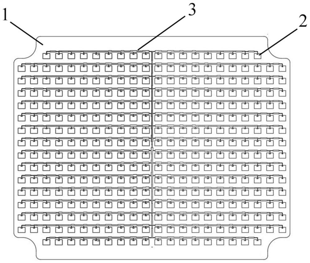
[0026] see Figure 1-2 As shown, a high-performance microstrip array antenna includes a substrate 1. The substrate 1 includes an upper substrate and a lower substrate disposed on the bottom surface of the upper substrate. The bottom surface of the lower substrate is provided with a metal ground layer. The structure of the substrate is a prior art and will not be repeated here.

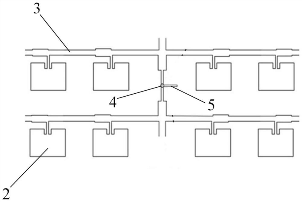
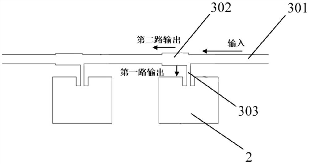
[0027] The top surface of the upper substrate is arranged in a rectangular array with a number of microstrip radiation patches 2 (radiation units), that is, the array spacing in the horizontal direction is the same, and the array spacing in the vertical direction is the same, and the number of microstrip radiation patches 2 arrays in the horizontal direction is the same as that in the vertical direction. are even numbers. It should be noted that, during actual production, the number of arrays in the horizontal direction and the number of arrays in the vertical direction of the microstrip radiation pat...

Embodiment 2

[0035] see Figure 1-4 As shown, on the basis of Example 1, the microstrip radiation patch is rectangular 2, and the horizontal direction and vertical direction of the rectangular array of microstrip radiation patches 2 are respectively consistent with the length direction and width direction of the microstrip radiation patch 2. Optionally, the substrate 1 is rectangular, and the horizontal direction and vertical direction of the rectangular array of microstrip radiation patches 2 are respectively consistent with the length direction and width direction of the substrate 1 .

[0036] In the rectangular array of microstrip radiation patches 2, the spacing between adjacent microstrip radiation patches 2 in the horizontal direction is equal to the spacing between adjacent microstrip radiation patches 2 in the vertical direction, ensuring that each single microstrip radiation patch 2 There is a 360° phase difference at the center frequency point.

[0037] The power distribution ne...


PUM

PropertyMeasurementUnit
sizeaaaaaaaaaa

Abstract

A high-performance microstrip array antenna disclosed by the present invention comprises a substrate, the substrate comprises an upper layer substrate and a lower layer substrate arranged on the bottom surface of the upper layer substrate, the bottom surface of the lower layer substrate is provided with a metal grounding layer, and the top surface of the upper layer substrate is provided with a plurality of microstrip radiation patches in a rectangular array. The number of arrays of the microstrip radiation patches in the horizontal direction and the number of arrays of the microstrip radiation patches in the vertical direction are both even numbers. Metallized via holes are formed in the positions, located in the centers of matrixes of the microstrip radiation patches, of the substrate. Metal probes are welded in the metalized through holes, the metal probes are connected with all the microstrip radiation patches through a power distribution network arranged on the top face of the upper-layer substrate, the metal probes are used for feeding the microstrip array antenna, and the power distribution network is used for distributing microwave signals to all the microstrip radiation patches. And a microstrip stub is arranged at the joint of the metal probe and the top surface of the upper-layer substrate. According to the invention, the microstrip stub line is optimally designed at the feed center point, so that the parasitic inductive reactance of the feed metalized via hole is effectively eliminated, and the impedance matching characteristic at the feed position is improved.

Description

technical field [0001] The invention relates to the technical field of communication antennas, in particular to a high-performance microstrip array antenna. Background technique [0002] An array antenna is an antenna system composed of many identical single antennas (such as symmetrical antennas) arranged in a certain order, also known as an antenna array, and the independent units that form the antenna array are called array elements or antenna units. If the array elements are arranged on the same line or on the same plane, it is called a linear array or a planar array. In the existing array antennas, the feed metal vias are prone to generate parasitic inductance, and the impedance matching characteristics of the antenna are poor, so the maximum power transmission cannot be obtained, and even the power distribution network may be damaged. Contents of the invention [0003] The purpose of the present invention is to provide a high-performance microstrip array antenna in ...

Claims


Application Information

Patent Timeline
Patent Type & Authority Applications(China)
IPC IPC(8): H01Q1/38H01Q1/48H01Q1/50H01Q21/06
CPCH01Q1/38H01Q1/48H01Q1/50H01Q21/065H01Q21/0006
Inventor 叶楠李冬青张东华陈建军
Owner 中电科创智联(武汉)有限责任公司
Why Eureka
Try Eureka