Method for improving welding performance of direct-current relay

A DC relay and welding performance technology, applied in welding equipment, resistance welding equipment, metal processing equipment, etc., can solve the problems of increased current consumption, low heat transfer efficiency, and slow production cycle, so as to promote welding process, Effect of improving heat transfer efficiency and increasing production efficiency

Pending Publication Date: 2022-05-17
施生面
View PDF0 Cites 1 Cited by
  • Summary
  • Abstract
  • Description
  • Claims
  • Application Information

AI Technical Summary

Problems solved by technology

If the thickness of the lower yoke plate is too large, a higher current is required, which requires a higher power resistance welding machine. Excessively high current consumes more power, and the heat transfer efficiency is low, and the welding time is long, resulting in a slow production cycle.

Method used


Image

  • Method for improving welding performance of direct-current relay
  • Method for improving welding performance of direct-current relay
  • Method for improving welding performance of direct-current relay

Examples


Embodiment 1

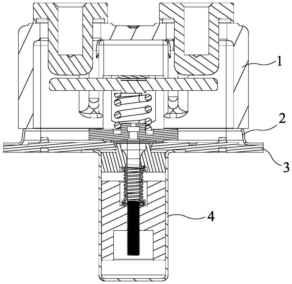
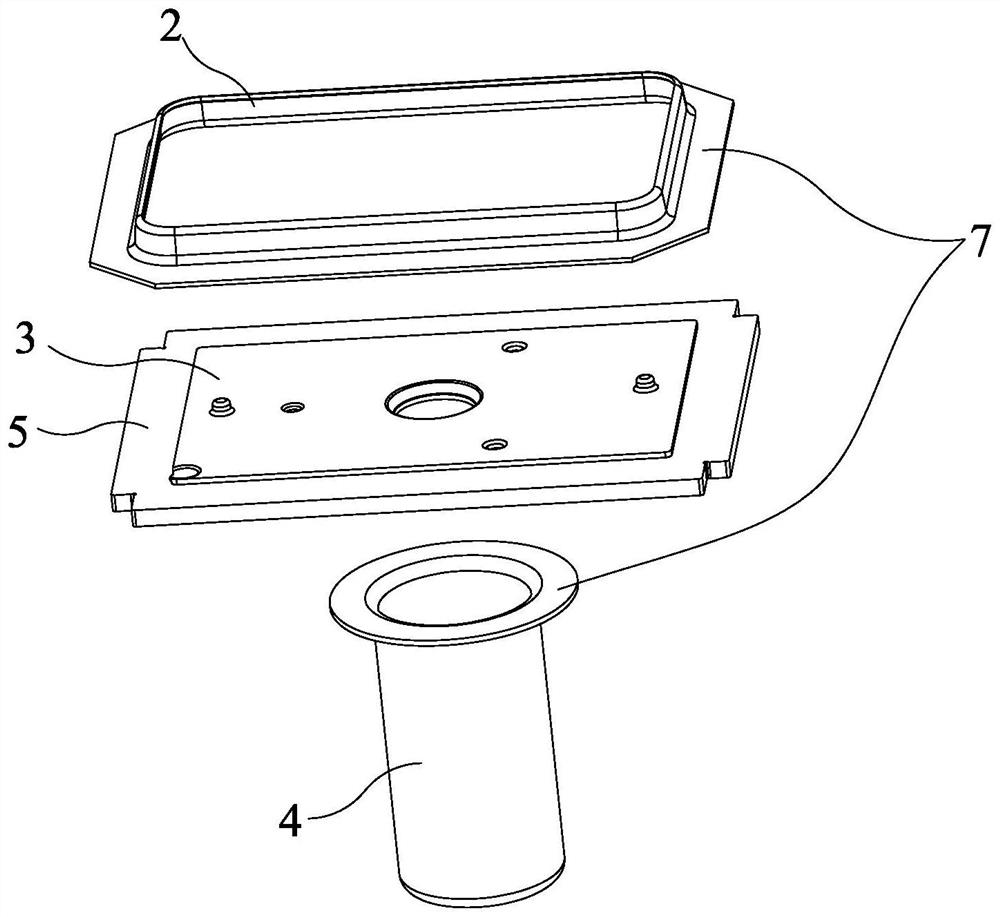
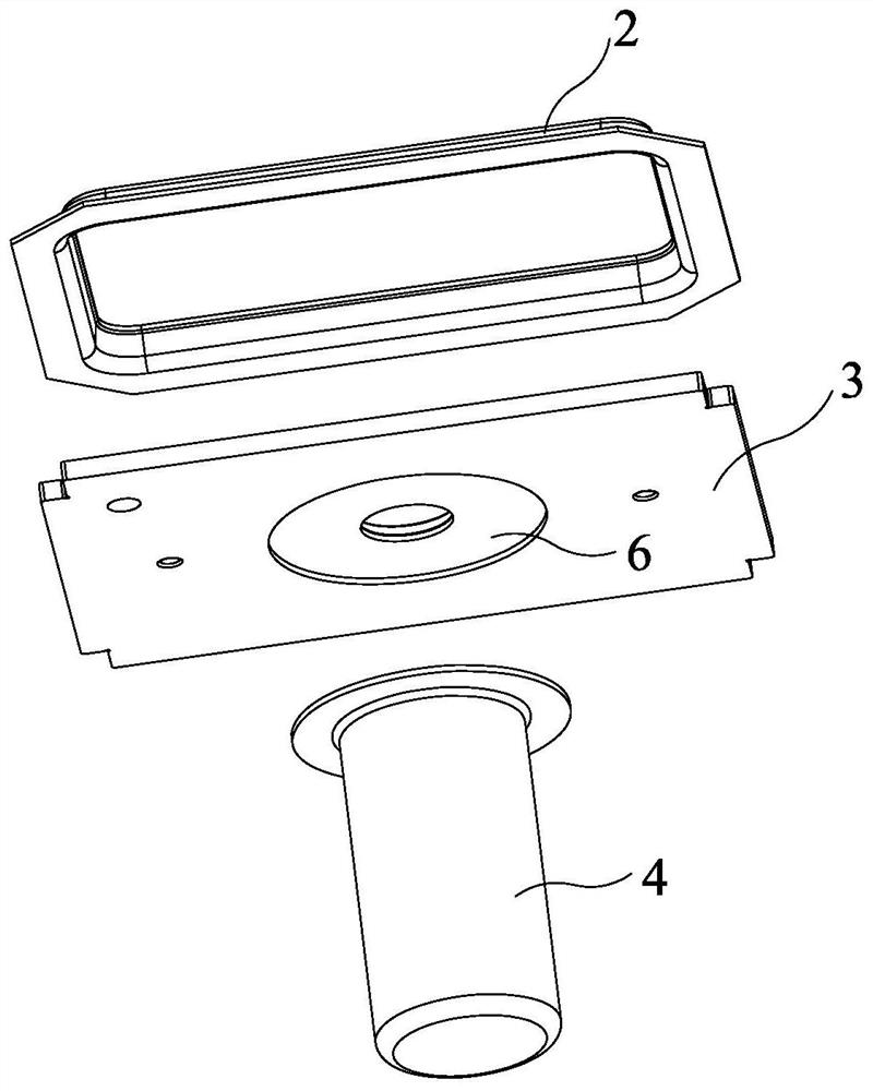
[0025] Such as figure 1 As shown, the present invention provides a method for improving the welding performance of a DC relay, involving a ceramic cover assembly 1, a frame piece 2, a lower yoke plate 3 and a metal shell 4, such as figure 2 As shown, the thickness of one side of the lower yoke plate 3 is reduced at the connection position relative to the frame piece 2 to form a first sinker 5. The shape of the first sinker 5 is the same as that of the connection point of the frame piece 2, which can be Square, circular, or other shapes, the frame piece 2 and the metal shell 4 each form an outward flange 7 at the joint to be welded. For the frame piece 2, the flange of the frame piece 2 is square , so the shape of the first sinking groove 5 corresponds to a square, and the first sinking groove 5 is located at the edge of the lower yoke plate 3, and the frame piece 2 is fitted into the first sinking groove 5 and welded; as image 3 As shown, the thickness of the other side of ...

Embodiment 2

[0031] Such as Figure 4 to Figure 6 As shown, the difference between this embodiment and Embodiment 1 is that the first sinking groove 5 is located in the middle of the lower yoke plate 3 instead of the edge, so that the outer circumference of the joint of the frame piece 2 is more A limiting edge is provided so that the joint of the frame piece 2 can be completely embedded in the first sinking groove 5, which is more stable.


PUM


Abstract

The invention discloses a method for improving the welding performance of a direct-current relay, and relates to a lower yoke plate, a metal shell and a frame sheet, the method comprises the frame sheet welding step: firstly, the thickness of one surface, opposite to the frame sheet, of the lower yoke plate is thinned, a first sinking groove is machined, and the shape of the first sinking groove is matched with the connecting position of the frame sheet; then aligning the frame sheet to be connected with the first sinking groove and then embedding the frame sheet into the first sinking groove in a matching manner; and finally welding the frame sheet and the first sinking groove together through electric resistance welding. And a metal shell welding step: firstly, the thickness of one surface, opposite to the metal shell, of the lower yoke plate is thinned, a second sinking groove is processed, the shape of the second sinking groove is matched with that of the joint of the metal shell, then the metal shell to be connected is aligned with the second sinking groove and then is embedded into the second sinking groove in a matched manner, and finally, the metal shell and the second sinking groove are welded together through electric resistance welding. The sinking groove is designed to reduce the thickness of the lower yoke plate so as to reduce the current of the welding machine, materials can be saved, and the production efficiency is improved.

Description

technical field [0001] The invention belongs to the technical field of relays, in particular to a method for improving the welding performance of a DC relay. Background technique [0002] High-voltage DC relays are generally composed of ceramic cover components, frame pieces, lower yoke plates, metal shells, and exhaust pipes. In the existing schemes, one side of the lower yoke plate is laser-welded with frame pieces, and the ceramic cover components are covered. On the frame piece, the metal shell is laser welded on the other side of the lower yoke plate, so that a sealed cavity is formed between the ceramic cover assembly, the lower yoke plate, and the metal shell. However, this process method is gradually eliminated, and the more cost-effective resistance welding method is adopted. [0003] Resistance welding refers to the method of using the resistance heat generated by the current passing through the weldment and the contact as the heat source to locally heat the weldm...

Claims


Application Information

Patent Timeline
Patent Type & Authority Applications(China)
IPC IPC(8): B23K11/36
CPCB23K11/36
Inventor 施生面
Owner 施生面
Why Eureka
Try Eureka