
Cloth heat sublimation equipment

A dye-sublimation and fabric technology, applied in thin material processing, printing, printing machines, etc., can solve problems such as deformation, fabric printing pattern deformation, and wrinkles, and achieve high automation, precise control of feeding speed, and labor cost savings.

Pending Publication Date: 2022-05-17
BETA TECH LLC
View PDF0 Cites 0 Cited by
  • Summary
  • Abstract
  • Description
  • Claims
  • Application Information

AI Technical Summary

Problems solved by technology

[0004] However, the existing technology ignores that the characteristics of the cloth are different from that of the paper material, especially when the cloth roll is relatively large, it needs a greater force to pull the cloth to make the cloth roll rotate, which will cause the cloth to be damaged. When the material is fed into the sublimation machine, it is stretched and deformed, resulting in deformation of the printed pattern on the sublimated fabric
[0005] Moreover, in the prior art, the thermally-transferred fabric hangs freely on the ground, which is easy to cause wrinkles during transportation, and adds additional cumbersome steps to the subsequent cutting process that require continuous processing of wrinkles

Method used


Image

  • Cloth heat sublimation equipment
  • Cloth heat sublimation equipment

Examples


Embodiment Construction

[0043] In order to enable those skilled in the art to better understand the solutions of the present invention, the following will clearly and completely describe the technical solutions in the embodiments of the present invention in conjunction with the drawings in the embodiments of the present invention. Obviously, the described embodiments are only It is an embodiment of a part of the present invention, but not all embodiments. Based on the embodiments of the present invention, all other embodiments obtained by persons of ordinary skill in the art without making creative efforts shall fall within the protection scope of the present invention.

[0044] It should be noted that the terms "first" and "second" in the description and claims of the present invention and the above drawings are used to distinguish similar objects, but not necessarily used to describe a specific sequence or sequence. It is to be understood that the data so used are interchangeable under appropriate ...


PUM


Abstract

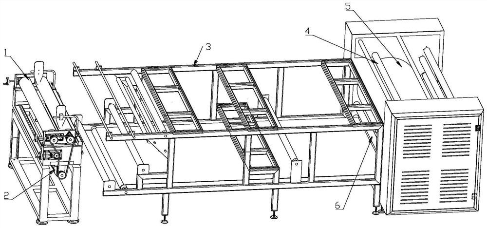
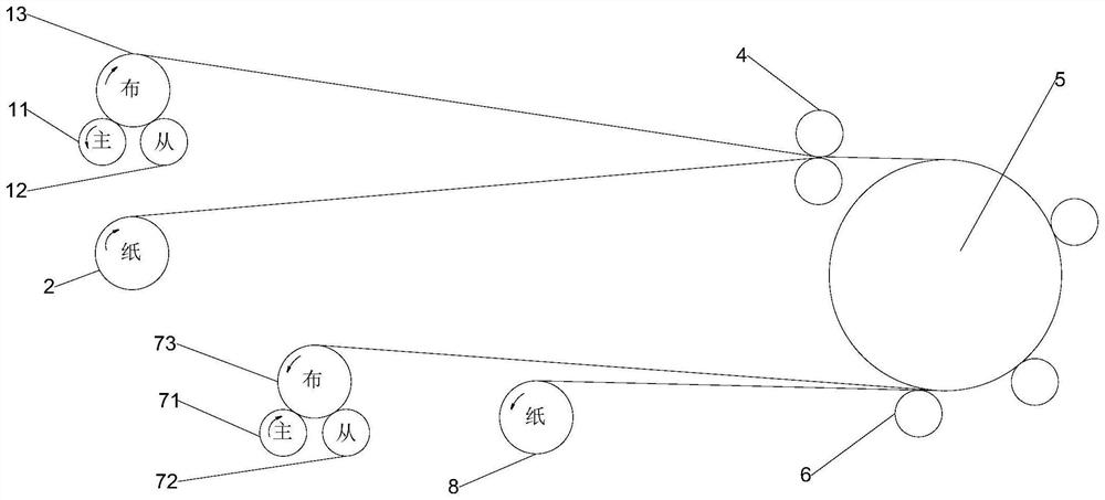
The invention discloses cloth thermal dye sublimation equipment which comprises a thermal dye sublimation paper conveying device, a cloth conveying device, a platform, an input reel, a thermal dye sublimation ironing cylinder, an output reel and a power assembly mechanism, the thermal dye sublimation paper conveying device and the cloth conveying device are arranged at one end of the platform, and the input reel, the thermal dye sublimation ironing cylinder and the output reel are arranged at the other end of the platform. The power assembly mechanism is configured to drive the input reel, the heat sublimation ironing cylinder and the output reel to rotate; the input reel is configured to pull a layer of thermal sublimation paper unfolded from a paper material supply roll at the thermal sublimation paper conveying device and a layer of cloth unfolded from a cloth supply roll at the cloth conveying device in the rotating process of the input reel, so that the thermal sublimation paper to be subjected to thermal transfer printing and the cloth to be subjected to thermal transfer printing reach the thermal sublimation ironing cylinder in a stacked state. According to the cloth heat sublimation equipment, the flatness and looseness of the cloth in the heat transfer printing process can be kept, and printing and loading pattern deformation caused by pulling shrinkage of the cloth in the heat transfer printing process is avoided.

Description

technical field [0001] The invention relates to the field of thermal transfer printing equipment, in particular to a fabric thermal sublimation equipment. Background technique [0002] Sublimation heat transfer printing is an emerging printing process widely used in polyester fiber garment production, which takes the mirror image of the high-resolution picture ready to be printed on the garment, prints it on the sublimation paper with sublimation ink, and then The patterned side of the sublimation paper is opposite to the fabric, and they are sent into the sublimation equipment together. In the sublimation equipment, the sublimation ink on the sublimation paper is sublimated by heat, and the adhesion rate of the gaseous sublimation ink to the polyester fiber is much higher than that of the paper fiber. Printed paper layered on fabric. Obviously, the lamination state of the cloth and heat transfer paper affects the printing effect on the cloth after sublimation heat transfe...

Claims


Application Information

Patent Timeline
Patent Type & Authority Applications(China)
IPC IPC(8): B65H16/10B65H16/08B65H18/02B65H18/16B65H20/02B65H23/26B65H37/00B41F16/00B41F16/02
CPCB65H16/10B65H16/08B65H18/025B65H18/16B65H20/02B65H37/00B65H23/26B41F16/02B41F16/0026B65H2701/1133B65H2701/174B65H2801/21
Inventor 朱俊杰房建生彭明辉
Owner BETA TECH LLC
Learn More