Closed-loop temperature control variable-position heat source continuous fiber composite material forming equipment

A continuous fiber and composite material technology, which is applied in the field of closed-loop temperature-controlled variable-position heat source continuous fiber composite material forming equipment, can solve the problems of small heating area, low heating temperature, and large volume, and achieve high efficiency.

Active Publication Date: 2022-05-24
ZHEJIANG UNIV
View PDF6 Cites 0 Cited by
  • Summary
  • Abstract
  • Description
  • Claims
  • Application Information

AI Technical Summary

Problems solved by technology

[0005] Traditional heat sources mainly use high-temperature gas, infrared heat source, laser heat source, etc. High-temperature gas generally uses chemically inactive nitrogen, which has low energy utilization rate and uncontrollable temperature. Infrared heat sources mainly include halogen heating tubes and quartz infrared heaters. The heating temperature is relatively low and the heating time is long. The laser heat source has attracted wide attention due to its high energy conversion rate and controllable temperature. However, it has limitations such as large volume and high risk factor. The development of pulsed xenon lamp combines laser and The advantages of infrared lamp heating have the advantages of rapid heating and cooling without heat residue, high temperature, small size, small heating area, good safety performance, etc., becoming one of the most potential heating methods

Method used


Image

  • Closed-loop temperature control variable-position heat source continuous fiber composite material forming equipment
  • Closed-loop temperature control variable-position heat source continuous fiber composite material forming equipment
  • Closed-loop temperature control variable-position heat source continuous fiber composite material forming equipment

Examples


Embodiment Construction

[0037] The present invention will be further described in detail below with reference to the accompanying drawings and embodiments. It should be pointed out that the following embodiments are intended to facilitate the understanding of the present invention, but do not have any limiting effect on it.

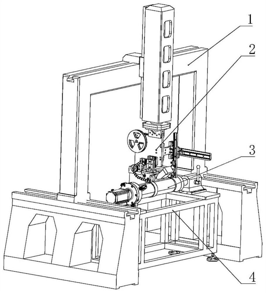
[0038] like figure 1 As shown in the figure, a closed-loop temperature-controlled variable-position heat source continuous fiber composite material molding equipment includes a gantry-type four-axis motion platform 1, an in-situ additive molding equipment based on a pulsed xenon lamp movable heat source 2, and a fiber molding with a temperature detection function. Module 3, the fiber forming module is installed on the desktop 4.

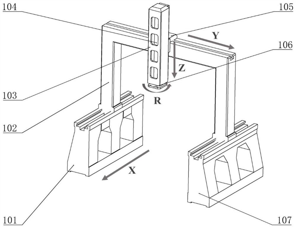
[0039] like figure 2As shown, the gantry type four-axis motion platform 1 includes a gantry column 102 slidably fixed on the first vibration isolation base 101 and the second vibration isolation base 2 107, and the upper end surface of the vibration ...


PUM


Abstract

The invention discloses closed-loop temperature control variable-position heat source continuous fiber composite material forming equipment. The closed-loop temperature control variable-position heat source continuous fiber composite material forming equipment comprises a gantry type four-axis motion platform, in-situ additive forming equipment, a fiber forming module and a fiber forming module mounting table top, the gantry type four-axis motion platform is used for driving the in-situ additive forming equipment to horizontally move in the X-axis direction, the Y-axis direction and the Z-axis direction and to rotate. The in-situ additive forming equipment comprises a suspension base plate, a charging tray, a fixed guide wheel, nitrogen blowing equipment, an adjustable guide compression roller assembly and an angle-adjustable pulse xenon lamp, wherein the charging tray, the fixed guide wheel, the nitrogen blowing equipment, the adjustable guide compression roller assembly and the angle-adjustable pulse xenon lamp are fixed to the plate face of the suspension base plate. The fiber forming module comprises a motor and a tip cone, an output shaft of the motor is coaxially matched with a rotary connecting plate, a three-jaw chuck is fixed to the rotary connecting plate, and a detachable forming base mold with an annular temperature detection prefabricated part is coaxially clamped between the three-jaw chuck and the tip cone. According to the invention, the position and angle of the heat source are adjustable, and temperature detection and heat history recording functions are realized.

Description

technical field [0001] The invention relates to the technical field of high-performance continuous fiber reinforced resin, in particular to a closed-loop temperature-controlled variable displacement heat source continuous fiber composite material molding equipment. Background technique [0002] Advanced resin-based fiber-reinforced composite materials have been widely used in aerospace, high-pressure vessels and other fields due to their unique advantages such as high specific strength and specific stiffness, strong designability, fatigue resistance, and good corrosion resistance. As the fastest growing and most efficient molding technology in recent years, composite fiber / tape forming technology has shown great advantages and potential in reducing manufacturing cost and improving the performance of composite structural parts. [0003] In the fiber forming process, the resin in the prepreg wire must first be melted to realize the forming and laying. If the temperature is too...

Claims


Application Information

Patent Timeline
Patent Type & Authority Applications(China)
IPC IPC(8): B29C64/264B29C64/295B29C64/393B29C64/40B29C64/245B29C64/20B33Y10/00B33Y30/00B33Y40/00B33Y50/02
CPCB29C64/264B29C64/295B29C64/393B29C64/40B29C64/245B29C64/20B33Y10/00B33Y30/00B33Y40/00B33Y50/02Y02T50/40
Inventor 栾丛丛纪毓杨姚鑫骅丁泽泉徐冠华傅建中
Owner ZHEJIANG UNIV
Why Eureka
Try Eureka