A kind of pipeline type shaft inner wall pouring method

A pipelined, vertical shaft technology, applied in vertical shaft equipment, earthwork drilling, wellbore lining, etc., can solve the problems of prolonged construction period, inability to climb, difficult to control the accuracy of formwork, etc., to improve construction quality, construction efficiency and construction accuracy. high effect

Active Publication Date: 2022-08-02
BEIJING NO 3 CONSTR ENG
View PDF12 Cites 0 Cited by
  • Summary
  • Abstract
  • Description
  • Claims
  • Application Information

AI Technical Summary

Problems solved by technology

[0005] 1. It is necessary to set support points (such as "anchor device" in CN102704674B) on the lining wall that has been finalized to support the climbing formwork system, which leads to a further extension of the construction period (you need to wait for the final setting of the concrete, and you need to complete the climbing formwork every time you climb The system is detached from the current support point and connected to the next support point), and the lining wall is damaged;
[0006] 2. Every time you climb, you need to withdraw the formwork (withdrawing the formwork refers to letting the formwork retreat in the horizontal direction to separate from the concrete. If the formwork is not withdrawn, the final set concrete will make the cylindrical shaft formwork unable to climb). The formwork is a cylindrical structure instead of a flat plate. Therefore, the formwork must be removed first if the formwork is to be removed, and the formwork needs to be re-installed after climbing. The workload is large and the construction period is prolonged, and the accuracy of the formwork is difficult to control;
[0007] 3. Since the opposite pull screw cannot be used, the support effect on the formwork is poor, and it cannot effectively resist the mold expansion force;
[0008] 4. Reinforcement cages need to be tied in advance before construction of climbing formwork

Method used


Image

  • A kind of pipeline type shaft inner wall pouring method
  • A kind of pipeline type shaft inner wall pouring method

Examples


Embodiment Construction

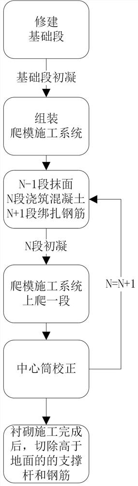
[0046] like figure 1 As shown in the figure, a method for pouring the inner wall of a pipeline type shaft adopts a climbing formwork construction system to construct the shaft lining from bottom to top in the shaft, and includes the following steps:

[0047] Step 1: Divide the shaft lining into multiple construction sections with gradually increasing serial numbers from bottom to top from the beginning, and the first construction section is recorded as the foundation section; For the diameter tube structure, the height of each construction section with serial number greater than one is the same and less than the height of the variable diameter tube, and is recorded as the air section;

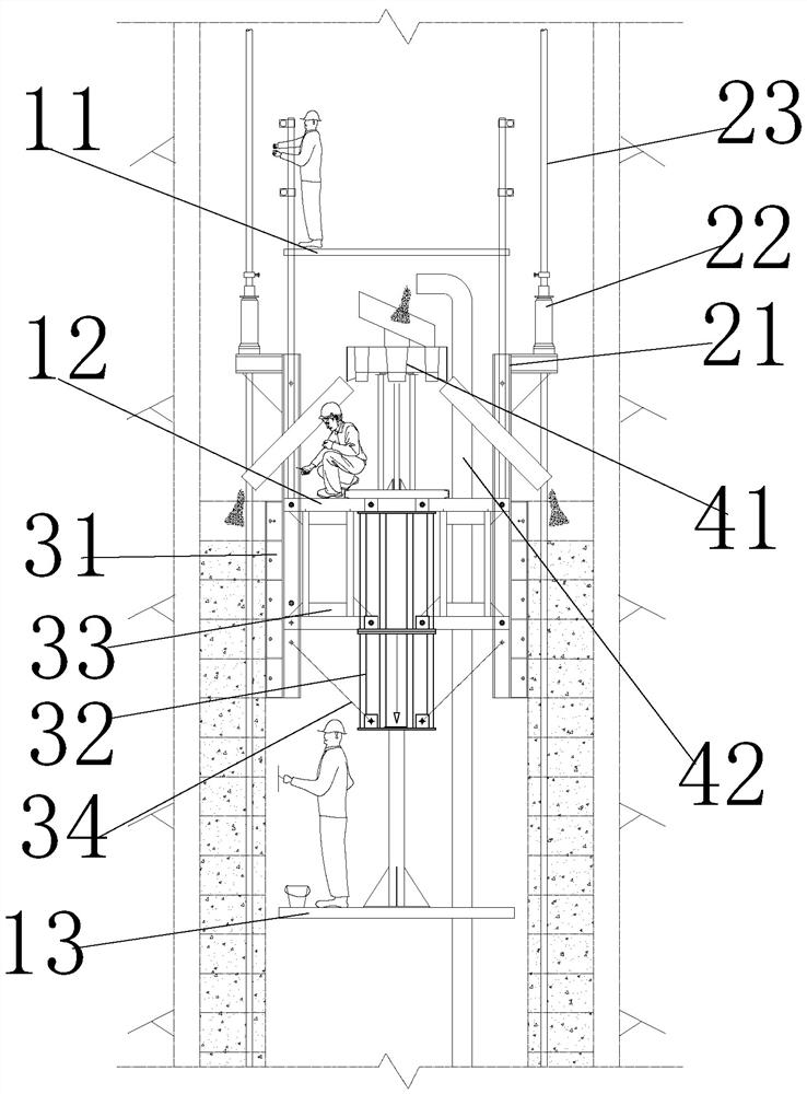
[0048] The construction of the foundation section is completed, and the concrete of the foundation section is poured with the formwork 31 that has not been assembled into the climbing formwork construction system.

[0049] Step 2: After the initial setting of the foundation section, remove the...


PUM


Abstract

The invention relates to the technical field of shaft lining, and discloses a pipeline-type shaft inner wall pouring method, which is used for bottom-up construction of the shaft lining in the shaft; The construction system integrates the construction equipment and working platform required for the construction of shaft lining according to the construction sequence, and allows multiple processes to be constructed at the same time, which significantly shortens the construction period; the whole system is supported by through-core jacks and support rods, which is different from the traditional climbing formwork system. In contrast, without relying on the load-bearing of the concrete structure, the currently poured concrete can climb after the initial setting, and the formwork is supported by the elastic central cylinder, and the formwork is enclosed into a variable-diameter cylinder structure with upper thickness and lower thickness, so that climbing does not need to retreat. The mold can be carried out smoothly; the laser leveling device and the locker ensure that the top elevations of each lifting frame are consistent during climbing, and the tensioning connector ensures that after each climbing is completed, the center cylinder and the shaft are coaxial, so that the construction accuracy is extremely high.

Description

technical field [0001] The invention relates to the technical field of wellbore lining, in particular to a method for pouring the inner wall of a pipeline type shaft. Background technique [0002] The shaft is an important passage connecting the underground structure with the ground, and has its special functions, such as ventilation, emergency escape passage, etc. For the shaft, it needs a thick lining wall to resist the pressure of the formation and prevent the leakage of external water to the ground. inside the well. After the shaft is excavated, the diameter of the hole is small and the depth is deep. It is neither convenient nor scientific to set up scaffolding for lining construction, and it is inconvenient to use vertical transportation equipment for the support and dismantling of the formwork, so there are great difficulties in construction. [0003] Since the structure of the shaft is similar to a chimney, some people try to use a climbing formwork construction pro...

Claims


Application Information

Patent Timeline
Patent Type & Authority Patents(China)
IPC IPC(8): E21D5/11E21D5/12
CPCE21D5/11E21D5/12Y02E10/20
Inventor 李春龙张世博张飞苗海良刘海强邓磊马涛崔正茂丁涛杨帆
Owner BEIJING NO 3 CONSTR ENG
Why Eureka
Try Eureka