Winding and unwinding system, management and control method, control unit and computer storage medium
A technology of winding and unwinding, control, applied in electrode manufacturing, electrical components, final product manufacturing, etc., can solve problems such as quality deterioration
Active Publication Date: 2022-05-24
CONTEMPORARY AMPEREX TECH CO
8 Cites 0 Cited by
AI-Extracted Technical Summary
Problems solved by technology
Therefore, one purpose of this application is to propose a pole piece winding and unwinding system, a pole piece management and control method, a control u...
Method used
[0050] During the first charging and discharging process of the lithium-ion battery, the electrode material and the electrolyte react at the solid-liquid phase interface to form a passivation layer covering the surface of the electrode material. This passivation layer has the characteristics of a solid electrolyte, an electronic insulator but an excellent conductor of lithium ions. Lithium ions can be freely inserted and extracted through the passivation layer, so the passivation layer is called "solid electrolyte interface (SEI, Solid Electrolyte Interface) film". The formation of the SEI film consumes part of the lithium ions. Therefore, lithium supplementation is usually performed on the pole piece to compensate for the consumption of lithium ions during the first charge and discharge.
[0064] The first temperature sensor 1106 is placed close to the pole piece cylinder 1105 to more accurately monitor the temperature of the pole piece. The first gas...
Abstract
The invention provides a winding and unwinding system, a control method, a control unit and a computer storage medium. The winding and unwinding system comprises a winding and unwinding box, a cooling unit and a control unit, the winding and unwinding box comprises a box body, a box door, a pole piece discharging port, a rotating shaft, a pole piece cylinder and a first temperature sensor, wherein the box body and the box door jointly limit a box space of the winding and unwinding box; the pole piece discharging port is formed in the side face of the box body; the rotating shaft is arranged in the middle of the box space; the first gas detector is used for monitoring the oxygen concentration in the winding and unwinding box, the gas inlet is formed in the lower portion of the box body, the gas outlet is formed in the upper portion of the box body, the cooling unit is communicated with the gas inlet, and the control unit controls the cooling unit to adjust the temperature of the pole piece and the oxygen concentration in the winding and unwinding box according to the temperature of the pole piece and the oxygen concentration in the winding and unwinding box. Pole piece quality is guaranteed and potential safety hazards are reduced.
Application Domain
Electrode manufacturing processesFinal product manufacture +1
Technology Topic
PhysicsCooling Units +6
Image
Examples
- Experimental program(1)
Example Embodiment
[0042] The embodiments of the technical solutions of the present application will be described in detail below with reference to the accompanying drawings. The following examples are only used to illustrate the technical solutions of the present application more clearly, and are therefore only used as examples, and cannot be used to limit the protection scope of the present application.
[0043] Unless otherwise defined, all technical and scientific terms used herein have the same meaning as commonly understood by one of ordinary skill in the technical field of this application; the terms used herein are for the purpose of describing specific embodiments only, and are not intended to be Limiting this application; the terms "comprising" and "having" and any variations thereof in the specification and claims of this application and the above description of the drawings are intended to cover non-exclusive inclusion.
[0044] In the description of the embodiments of the present application, the technical terms "first", "second", etc. are only used to distinguish different objects, and should not be understood as indicating or implying relative importance or implying the number, specificity and quantity of indicated technical features. Sequential or primary and secondary relationships.
[0045] Reference herein to an "embodiment" means that a particular feature, structure, or characteristic described in connection with the embodiment can be included in at least one embodiment of the present application. The appearances of the phrase in various places in the specification are not necessarily all referring to the same embodiment, nor a separate or alternative embodiment that is mutually exclusive with other embodiments. It is explicitly and implicitly understood by those skilled in the art that the embodiments described herein may be combined with other embodiments.
[0046] In the description of the embodiments of the present application, the term "and/or" is only an association relationship for describing associated objects, indicating that there may be three relationships, such as A and/or B, which may indicate that A exists alone, and A exists at the same time and B, there are three cases of B alone. In addition, the character "/" in this text generally indicates that the related objects are an "or" relationship.
[0047] In the description of the embodiments of the present application, the term "plurality" refers to two or more (including two), similarly, "multiple groups" refers to more than two groups (including two groups), and "multiple sheets" refers to of two or more pieces (including two pieces).
[0048] In the description of the embodiments of the present application, the technical terms "center", "longitudinal", "horizontal", "length", "width", "thickness", "top", "bottom", "front", "rear", "left", "right", "vertical" "Horizontal", "top", "bottom", "inside", "outside", "clockwise", "counterclockwise", "axial", "radial", "circumferential", etc. indicate the orientation or positional relationship based on those shown in the accompanying drawings The orientation or positional relationship is only for the convenience of describing the embodiments of the present application and simplifying the description, rather than indicating or implying that the device or element referred to must have a specific orientation, be constructed and operated in a specific orientation, and therefore cannot be understood as implementing the present application. example limitations.
[0049] In the description of the embodiments of the present application, unless otherwise expressly specified and limited, the technical terms "installation", "connection", "connection", "fixed" and other terms should be understood in a broad sense, for example, it may be a fixed connection or a fixed connection. The connection can be disassembled or integrated; it can also be a mechanical connection or an electrical connection; it can be a direct connection or an indirect connection through an intermediate medium, and it can be the internal communication between the two elements or the interaction relationship between the two elements. Those of ordinary skill in the art can understand the specific meanings of the above terms in the embodiments of the present application according to specific situations.
[0050] During the first charge-discharge process of a lithium-ion battery, the electrode material reacts with the electrolyte at the solid-liquid phase interface to form a passivation layer covering the surface of the electrode material. This passivation layer has the characteristics of a solid electrolyte and is an electronic insulator, but an excellent conductor of lithium ions. Lithium ions can be inserted and extracted freely through the passivation layer, so the passivation layer is called "Solid Electrolyte Interface (SEI, Solid Electrolyte Interface) film". The formation of the SEI film consumes part of the lithium ions. Therefore, currently, the pole pieces are usually supplemented with lithium to make up for the consumption of lithium ions in the first charge and discharge.
[0051] The applicant has noticed that during the winding or unwinding process of the supplemented lithium pole piece, the supplemented lithium is easily reacted with air. The reaction generates a lot of heat and lasts for a long time, which will cause the temperature of the pole piece to be too high, thereby affecting the quality of the pole piece and bringing about potential safety hazards.
[0052] In order to solve the problem that the temperature of the pole piece increases during the rewinding and unwinding process, the applicant has designed a pole piece rewinding and unwinding system, which includes a temperature sensor, a cooling unit and a control unit. The control unit controls the temperature sensor according to the sensing result of the temperature sensor. The cooling unit regulates the temperature in the take-up and unwind box.
[0053] In addition, the applicant also noticed that the oxygen content in the rewinding and unwinding box will also change after the lithium-replenishing pole piece reacts with the air, and when the oxygen content in the reeling and unwinding box is not within a specific range, A reaction that destroys the quality of the pole piece will occur.
[0054] Based on the above considerations, in order to solve the problem of the quality deterioration of the pole piece during the rewinding and unwinding process, the applicant found through research that a gas detector can be installed in the rewinding and unwinding system to monitor the oxygen concentration in real time, and the control unit can detect the gas detector according to the detection of the gas detector. As a result, the cooling unit is controlled to adjust the oxygen concentration in the take-up and unwind box.
[0055] In such a rewinding and unwinding system, since the temperature and oxygen concentration can be controlled, the deterioration of the pole piece during the rewinding and unwinding process can be effectively improved.
[0056] For the convenience of description, the following embodiments take a winding and unwinding system 100 according to an embodiment of the present application as an example for description.
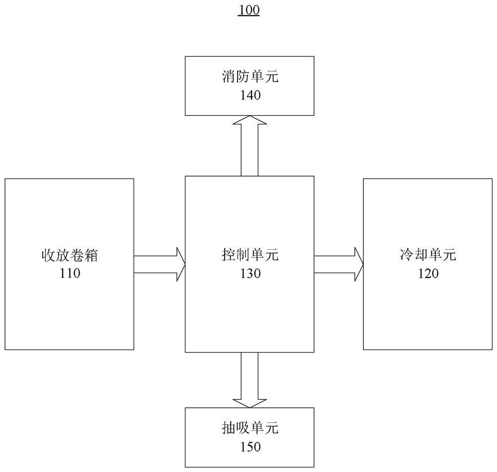
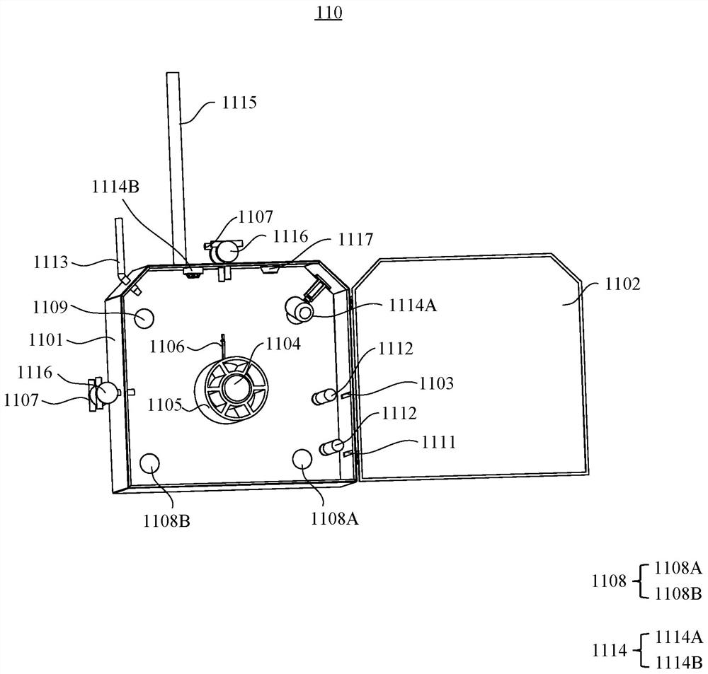
[0057] figure 1 This is a schematic block diagram of a rewinding and unwinding system 100 according to some embodiments of the present application. figure 2 This is a schematic structural diagram of the reel box 110 according to some embodiments of the present application. Please refer to figure 1 and figure 2 , some embodiments of the present application provide a rewinding and unwinding system 100 , including: a rewinding and unwinding box 110 , a cooling unit 120 and a control unit 130 . 1101 and the box door 1102, the pole piece discharge port 1103 arranged on the side of the box body 1101, the rotating shaft 1104 arranged in the middle of the box space, connected with the rotating shaft 1104 and driven by the rotating shaft 1104 to rewind and unwind the pole piece The pole piece cylinder 1105, the first temperature sensor 1106 for monitoring the temperature of the pole piece, the first gas detector 1107 for monitoring the oxygen concentration in the rewinding and unwinding box 110, the air inlet 1108 provided in the lower part of the box 1101 and The exhaust port 1109 is arranged on the upper part of the box 1101, the cooling unit 120 is communicated with the air inlet 1108, and the control unit 130 controls the temperature of the pole piece and the rewinding and unwinding of the cooling unit 120 according to the temperature of the pole piece and the oxygen concentration in the rewinding and unwinding box 110. The oxygen concentration in the tank 110 is adjusted.
[0058] For clarity and ease of understanding, refer to figure 2 The components included in the rewinding and unwinding box 110 will be described, but the shape, position and number of the components included in the winding and unwinding box 110 are not limited to figure 2 shown in the figure, but can be adjusted according to actual needs. For example, the shapes of the box body 1101 and the box door 1102 are not limited to figure 2 The shape shown in, but can be any shape that is convenient to accommodate the pole piece roll; the position of the pole piece outlet 1103 is not limited to figure 2 The specific position shown in the figure, but can be adjusted accordingly according to the specific process flow.
[0059] The pole piece can enter the take-up and unwinding box 110 from the outside of the pole piece discharge port 1103 and be connected to the pole piece cylinder 1105. The pole piece cylinder 1105 can cooperate with the rotating shaft 1104, and the rotating shaft 1104 can be driven by an external driving device to rotate and drive The pole piece drum 1105 rotates to realize the winding or unwinding of the pole piece.
[0060] The first temperature sensor 1106 , the first gas detector 1107 , the air inlet 1108 and the air outlet 1109 may be provided as one or more, and may be provided in different positions of the box body 1101 . The first temperature sensor 1106 may be a contact sensor or a non-contact sensor. The first temperature sensor 1106 may be a resistive sensor composed of a thermistor and an amplifier circuit. The first temperature sensor 1106 can be used to monitor the temperature of the pole piece in real time and send the monitored temperature value to the control unit 130 in time. The first gas detector 1107 can be used to monitor the oxygen concentration in the reel box 110 in real time, and send the monitored concentration value to the control unit 130 in time. The cooling unit 120 can be a gas cooling device, which can deliver gases with different temperatures and oxygen concentrations into the rewinding and unwinding box 110 through the air inlet 1108 to adjust the environment in the winding and unwinding box 110 .
[0061] As mentioned above, when the temperature of the pole piece is too high, the quality of the pole piece will deteriorate and there will be potential safety hazards. When the oxygen concentration in the reel box 110 is not within an appropriate range, it may cause an uncontrollable reaction of the pole piece. The rewinding and unwinding system 100 according to some embodiments of the present application can control the temperature of the pole piece and the oxygen concentration in the rewinding and unwinding box 110, thus preventing the pole piece from being overheated and the oxygen concentration exceeding the normal range during the rewinding and unwinding process Deterioration occurs, and the safety hazard in the production process can be reduced.
[0062] According to some embodiments of the present application, the first temperature sensor 1106 may be disposed close to the pole piece cylinder 1105 , and/or the first gas detector 1107 may be disposed on the top and/or side of the casing 1101 .
[0063] When the first gas detectors 1107 are respectively disposed on the top and side of the box 1101 , the first gas detectors 1107 may send the maximum value and/or the average value of the detected oxygen concentration values to the control unit 130 .
[0064] Setting the first temperature sensor 1106 close to the pole piece cylinder 1105 can monitor the pole piece temperature more accurately. The first gas detector 1107 monitors the oxygen concentration from different positions, so that the average oxygen concentration in the take-up and unwinding box 110 can be obtained more accurately and the maximum oxygen concentration can be easily monitored.
[0065] According to some embodiments of the present application, the air inlet 1108 may include a first air inlet 1108A and a second supplementary air outlet 1108B.
[0066] The first air inlet 1108A and the second supplementary air outlet 1108B may be disposed on both sides of the lower portion of the box body 1101 , respectively.
[0067] When necessary, the air intake volume can be increased through the second air supply port 1108B to speed up the adjustment of the gas environment and temperature in the unwinding and rewinding box 110 .
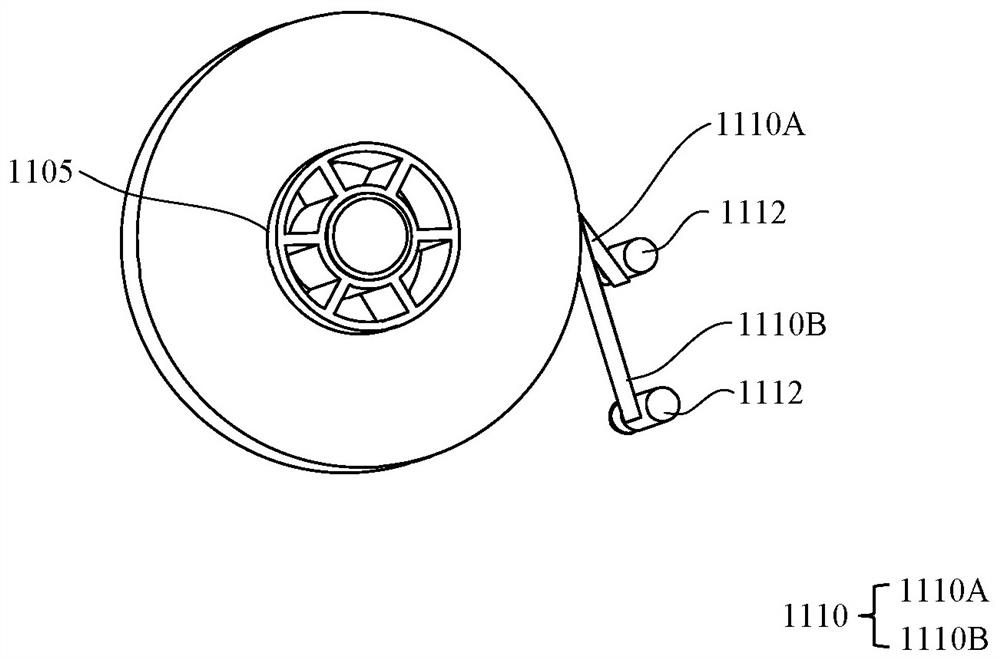
[0068] image 3 This is a schematic diagram of a pole piece roll according to some embodiments of the present application. Please refer to figure 2 and image 3According to some embodiments of the present application, the pole piece 1110 may further include a heat insulating film 1110B, and the reel box 110 may further include a heat insulating film outlet 1111 disposed on the side of the box body 1101 .
[0069] The pole piece 1110 may include a pole piece strip 1110A and a thermal barrier film 1110B. The pole piece strip 1110A may include an anode active material or a cathode active material. The heat shield film 1110B may include a polycarbonate (PC) material. When the pole piece 1110 does not include the heat insulating film 1110B, the heat insulating film outlet 1111 can be closed to ensure the airtight performance of the reel box 110 .
[0070] The heat insulating film 1110B can speed up the heat dissipation of the pole piece 1110 and better ensure the quality of the pole piece.
[0071] Please continue to refer to figure 2 , according to some embodiments of the present application, the rewinding and unwinding box 110 may further include: a pass roller 1112, which is arranged near the pole piece discharge port 1103 and/or the heat insulation film discharge port 1111, and is used in the winding or unwinding process. Support and stabilize the pole piece in the middle.
[0072] Using the roller 1112 to support the pole piece can reduce jitter and prevent the pole piece from rubbing against the pole piece discharge port 1103 and/or the heat insulation film discharge port 1111, thereby damaging the pole piece and causing the pole piece to heat up.
[0073] According to some embodiments of the present application, the reel box 110 may further include a fire sprinkler 1113 disposed on the top of the box 1101 and a fire sprinkler 1113 disposed on the top of the box 1101 for monitoring the flame and/or smoke in the take-up and unwind box 110 The fire detector 1114 and the unwinding and reeling system 100 may further include a fire fighting unit 140 which communicates with the fire sprinkler 1113 and is used for fire control of the reeling and unwinding box 110 .
[0074] Fire detectors 1114 may include flame detectors 1114A for detecting flames and/or smoke alarms 1114B for detecting smoke. The flame detector 1114A can be an infrared type flame detector or an infrared-ultraviolet hybrid type detector.
[0075] When a fire occurs in the rewinding and unwinding box 110, the fire fighting unit 140 can be used for fire control in time to ensure production safety.
[0076] According to some embodiments of the present application, the rewinding and unwinding box 110 may further include an air suction pipe 1115 disposed on the top of the box body 1101 and communicated with the unwinding and reeling box 110 , and a second air outlet for monitoring the hydrogen concentration in the unwinding and reeling box 110 . The gas detector 1116 , and the rewinding and unwinding system 100 may further include a suction unit 150 that communicates with the suction pipe 1115 and is used to adjust the hydrogen concentration in the rewinding and unwinding box 110 .
[0077] The second gas detectors 1116 may be arranged in one or more, and may be arranged in different positions of the box body 1101 . The second gas detector 1116 can be used to monitor the hydrogen concentration in the reel box 110 in real time, and send the monitored concentration value to the control unit 130 in time. The suction unit 150 can suck gas from the rewinding and unwinding reel box 110 via the air suction pipe 1115 to adjust the gas environment in the rewinding and unwinding reel box 110 .
[0078] The pole piece will react with the air during the tape running process to generate flammable gas hydrogen, and the hydrogen concentration in the rewinding and unwinding box 110 is controlled by the suction unit 150 to further reduce potential safety hazards.
[0079] According to some embodiments of the present application, the second gas detector 1116 is disposed on the top and/or the side of the box body 1101 .
[0080] When the second gas detectors 1116 are respectively disposed on the top and the side of the box body 1101 , the second gas detectors 1116 may send the maximum value and/or the average value of the detected hydrogen concentration values to the control unit 130 .
[0081] The second gas detector 1116 monitors the hydrogen concentration from different positions, so that the average hydrogen concentration in the take-up and unwinding box 110 can be obtained more accurately and the maximum hydrogen concentration can be easily monitored.
[0082] According to some embodiments of the present application, the take-up and unwind box 110 may further include a second temperature sensor 1117 for monitoring the temperature within the take-up and unwind box 110 .
[0083] The second temperature sensor 1117 may be a non-contact sensor. The second temperature sensor 1117 may be a resistive sensor composed of a thermistor and an amplifier circuit. The second temperature sensor 1117 can be used to monitor the temperature in the reel box 110 in real time and send the monitored temperature value to the control unit 130 in time.
[0084] The ambient temperature in the rewinding and unwinding box 110 can be monitored by the second temperature sensor 1117 while monitoring the temperature of the pole piece, so as to control the high temperature more effectively.
[0085] According to some embodiments of the present application, the second temperature sensor 1117 may be disposed on the top of the box body 1101 .
[0086] The second temperature sensor 1117 is disposed on the top of the box body 1101 to facilitate monitoring the maximum value of the ambient temperature in the rewinding and unwinding box 110 .
[0087] According to some embodiments of the present application, the first gas detector 1107 and the second gas detector 1116 may each include a detector body disposed outside the unwinding and reeling box 110 and a probe inserted inside the unwinding and unwinding box 110 .
[0088] The detector body is located outside the unwinding and reeling box 110, which can reduce the damage to the detector body caused by high temperature or dangerous situations such as fire alarms.
[0089] Figure 4 This is a schematic flowchart of a management and control method 1000 according to some embodiments of the present application. Please refer to Figure 4 Some embodiments of the present application provide a pole piece control method 1000 that can be applied to the rewinding and unwinding system 100 of the above-mentioned embodiments, including: when the pole piece temperature T is greater than or equal to a first threshold temperature T1 and less than or equal to a second threshold temperature T2 ( S1 ) and when the oxygen concentration C in the rewinding and unwinding box 110 is greater than or equal to the first threshold concentration C1 and less than or equal to the second threshold concentration C2 ( S2 ), control the cooling unit 120 to convey the temperature into the winding box 110 to be lower than the first threshold Temperature T1, and the oxygen concentration C is greater than or equal to the first threshold concentration C1 and less than or equal to the second threshold concentration C2 of the first gas, and the exhaust port 1109 is controlled to open.
[0090] When the pole piece temperature T is less than the first threshold temperature T1 and the oxygen concentration C in the reel box 110 is between the first threshold concentration C1 and the second threshold concentration C2 (S0), the pole piece can maintain good quality. The first threshold temperature T1 may be in the range of 40°C to 50°C. The second threshold temperature T2 may be, for example, 70°C. The first threshold concentration C1 may be in the range of 13% to 43%. The second threshold concentration C2 may be in the range of 30% to 60%.
[0091] When the temperature T of the pole piece is slightly higher, the temperature of the pole piece is lowered, and at the same time, the oxygen concentration C in the rewinding and unwinding box 110 is kept in an appropriate range, which can prevent the deterioration of the pole piece.
[0092] According to some embodiments of the present application, the management and control method 1000 may further include: when the pole piece temperature T is greater than or equal to the first threshold temperature T1 and less than or equal to the second threshold temperature T2 ( S1 ) and the oxygen concentration C in the reel box 110 is less than the first threshold temperature T1 At a threshold concentration C1 ( S3 ), the cooling unit 120 is controlled to deliver the second gas whose temperature is lower than the first threshold temperature T1 and the oxygen concentration is greater than or equal to the first threshold concentration C1 into the rewinding and unwinding box 110 , and the exhaust port 1109 is controlled to open .
[0093] When the temperature T of the pole piece is slightly higher and the oxygen concentration C in the rewinding and unwinding box 110 is low, the temperature of the pole piece is lowered and the oxygen concentration is increased at the same time, so as to prevent the deterioration of the pole piece.
[0094] According to some embodiments of the present application, the control method 1000 may further include: when the pole piece temperature T is greater than or equal to the first threshold temperature T1 and less than or equal to the second threshold temperature T2 ( S1 ) and the oxygen concentration C in the reel box 110 is greater than the first threshold temperature T1 At the time of the second threshold concentration C2 ( S4 ), the cooling unit 120 is controlled to deliver a third gas whose temperature is lower than the first threshold temperature T1 and the oxygen concentration is lower than or equal to the second threshold concentration C2 into the rewinding and unwinding box 110 , and the exhaust port 1109 is controlled to open .
[0095] When the temperature T of the pole piece is slightly higher and the oxygen concentration C in the take-up and unwinding box 110 is relatively high, the temperature of the pole piece is lowered, and the oxygen concentration is reduced at the same time, so as to prevent the deterioration of the pole piece.
[0096] According to some embodiments of the present application, the control method 1000 may further include: when the pole piece temperature T is greater than the second threshold temperature T2 ( S5 ), controlling the cooling unit 120 to transport the temperature into the rewinding and unwinding box 110 with a temperature lower than the first threshold temperature T1 And for the fourth gas whose oxygen concentration is lower than the third threshold concentration, the exhaust port 1109 is controlled to open, and a high temperature shutdown signal is issued.
[0097] When the pole piece temperature T is too high, the quality of the pole piece is seriously damaged. Cooling the pole piece and reducing the oxygen concentration in the rewinding and unwinding box 110 can prevent potential safety hazards caused by high temperature, and at the same time, a high temperature shutdown signal is issued to prevent poor quality pole pieces. The piece flows into the next production link.
[0098] According to some embodiments of the present application, the third threshold concentration may be smaller than the first threshold concentration C1.
[0099] When the pole piece temperature T is too high, fire is very likely to occur, so it is necessary to quickly reduce the oxygen concentration C in the rewinding and unwinding box 110 to eliminate potential safety hazards.
[0100] Figure 5 This is a schematic flowchart of a management and control method 1000 according to some embodiments of the present application. Please refer to Figure 5 , according to some embodiments of the present application, the control method 1000 may further include: when the fire detector 1114 detects flame and/or smoke (S6), controlling the fire fighting unit 140 to deliver the fire extinguishing medium to the reel box 110, and send out Dangerous shutdown signal.
[0101] The extinguishing medium may be a non-aqueous extinguishing medium.
[0102] When a fire has occurred, put out the fire in time to ensure production safety.
[0103] According to some embodiments of the present application, the control method 1000 may further include: when the hydrogen concentration H in the rewinding and unwinding box 110 is greater than or equal to the fourth threshold concentration H2 ( S7 ), controlling the suction unit 150 to pump from the winding box 110 Inhale gas and signal dangerous shutdown.
[0104] The fourth threshold concentration H2 may be in the range of 5% to 10%.
[0105] When the hydrogen concentration of the flammable gas is too high, an explosion is very likely to occur, so it is necessary to quickly reduce the hydrogen concentration H in the rewinding and unwinding box 110, and stop the operation in time.
[0106] According to some embodiments of the present application, the control method 1000 may further include: when the hydrogen concentration H in the box is greater than or equal to the fifth threshold concentration H1 and less than the fourth threshold concentration H2 and the temperature t in the rewinding and unwinding box 110 is lower than the third threshold temperature T3 At (S8), the suction unit 150 is controlled to suck gas from the rewinding and unwinding box 110, the cooling unit 120 is controlled to transport the fifth gas whose temperature is lower than the third threshold temperature T3 into the winding and unwinding box 110, and the exhaust port is controlled 1109 is open.
[0107] The fifth threshold concentration H1 may be in the range of 2% to 5%. The third threshold temperature T3 may be 75°C or more.
[0108] When the concentration of flammable gas hydrogen is high, it is necessary to reduce the hydrogen concentration H in the unwinding and reeling box 110, and at the same time reduce the temperature t in the unwinding and reeling box 110 to eliminate potential safety hazards.
[0109]According to some embodiments of the present application, the control method 1000 may further include: when the hydrogen concentration H in the rewinding and unwinding box 110 is greater than or equal to the fifth threshold concentration H1 and less than the fourth threshold concentration H2 and the temperature t in the rewinding and unwinding box 110 is greater than or equal to At the third threshold temperature T3 ( S9 ), the suction unit 150 is controlled to suck gas from the rewinding and unwinding box 110 , and the cooling unit 120 is controlled to transport the fifth gas whose temperature is lower than the third threshold temperature T3 into the winding box 110 , Control vent 1109 to open and signal a dangerous shutdown.
[0110] When the flammable gas hydrogen concentration is high and the temperature t in the unwinding and reeling box 110 is too high, explosion is very likely to occur, so it is necessary to quickly reduce the hydrogen concentration H in the unwinding and unwinding box 110, and at the same time cool down and stop work in time.
[0111] Please refer to figure 2 , in a specific embodiment, the rewinding and unwinding box 110 may include: a box body 1101 and a box door 1102 that together define a substantially rectangular box space, and a slit-shaped pole piece outlet 1103 disposed on the side of the box body 1101 and insulating film outlet 1111, over rollers 1112 arranged near the pole piece outlet 1103 and insulating film outlet 1111, first air inlets 1108A and second air inlets 1108A and second respectively arranged on both sides of the lower part of the box 1101 The air supply port 1108B, the exhaust port 1109 arranged on one side of the upper part of the box body 1101, the rotating shaft 1104 arranged in the middle of the box space, the pole piece cylinder 1105 connected with the rotating shaft 1104 and driven by the rotation of the rotating shaft 1104, close to the pole piece The first temperature sensor 1106 set on the drum 1105 for monitoring the temperature of the pole piece, the second temperature sensor 1117 set on the top of the box body 1101 for monitoring the temperature in the rewinding and unwinding box 110, respectively set on the top of the box body 1101 and The first gas detector 1107 on the side for monitoring the oxygen concentration in the unwinding and reeling box 110, the second gas detector 1116 on the top and the side of the box body 1101 for monitoring the hydrogen concentration in the unwinding and reeling box 110 respectively, A flame detector 1114A for detecting flames arranged on the top of the box 1101, a smoke alarm 1114B for detecting smoke arranged on the top of the box 1101, a fire sprinkler 1113 arranged on the top of the box 1101, and Exhaust duct 1115 at the top of 1101.
[0112] Image 6 This is a schematic diagram of the gas flow of the reel box 110 according to some embodiments of the present application. Please refer to Image 6 , when the airflow enters from the first air inlet 1108A and/or the second supplementary air port 1108B and is discharged from the exhaust port 1109, it can be formed in the reel box 110 such as Image 6 The airflow indicated by the arrow in the middle is used to adjust the temperature and gas concentration in the take-up and unwind box 110 .
[0113] The cooling unit 120 may communicate with the first air inlet 1108A and/or the second supplemental air outlet 1108B, the fire fighting unit 140 may communicate with the fire sprinkler 1113 , and the suction unit 150 may communicate with the exhaust duct 1115 . The control unit 130 may control the cooling unit 120, and/or the fire fighting unit 140, and/or the suction unit 150 to implement the pole piece control method 1000 of any of the above embodiments.
[0114] Some embodiments of the present application provide a control unit 130, including: at least one processor; and a memory communicatively connected to the at least one processor, wherein the memory stores instructions, and when the instructions are executed by the at least one processor, any one of the foregoing implementations is implemented Example pole piece control method 1000.
[0115] Some embodiments of the present application provide a computer storage medium, where a program is stored on the computer storage medium, and when the program is executed by a processor, the pole piece control method 1000 of any of the foregoing embodiments is implemented.
[0116] Finally, it should be noted that the above embodiments are only used to illustrate the technical solutions of the present application, but not to limit them; although the present application has been described in detail with reference to the foregoing embodiments, those of ordinary skill in the art should understand that: The technical solutions described in the foregoing embodiments can still be modified, or some or all of the technical features thereof can be equivalently replaced; and these modifications or replacements do not make the essence of the corresponding technical solutions deviate from the technical solutions of the embodiments of the present application. scope, which shall be included in the scope of the claims and description of the present application. In particular, as long as there is no structural conflict, each technical feature mentioned in each embodiment can be combined in any manner. The present application is not limited to the specific embodiments disclosed herein, but includes all technical solutions falling within the scope of the claims.
PUM


Description & Claims & Application Information
We can also present the details of the Description, Claims and Application information to help users get a comprehensive understanding of the technical details of the patent, such as background art, summary of invention, brief description of drawings, description of embodiments, and other original content. On the other hand, users can also determine the specific scope of protection of the technology through the list of claims; as well as understand the changes in the life cycle of the technology with the presentation of the patent timeline. Login to view more.