Detector optical machine assembly integrated with photosensitive surface conjugate diaphragm

A photoelectric detector and detector technology, which is applied in the direction of instruments, measuring devices, electromagnetic wave re-radiation, etc., can solve the complicated and complicated alignment of multi-element laser emission, the complicated and cumbersome adjustment process of optical axis, and the reduction of signal-to-noise ratio of received signals, etc. problems, to achieve the effect of strong anti-stray light and anti-electromagnetic interference, simple and easy to implement, and high degree of integration

Pending Publication Date: 2022-05-27
SOUTH WEST INST OF TECHN PHYSICS
View PDF0 Cites 1 Cited by
  • Summary
  • Abstract
  • Description
  • Claims
  • Application Information

AI Technical Summary

Problems solved by technology

When strong background light or short-distance backscattered light is incident on the structure in the receiving light path, it will produce stray light with complex diffuse reflection in the propagation direction, and the stray light incident on the photosensitive surface will significantly reduce the signal-to-noise ratio of the received signal, even Cause the detector to work in saturation, which seriously interferes with the normal operation of the detector
At present, in the single-pixel laser ranging radar system, a small aperture of the diaphragm is often set at the position of the first image plane in the receiving optical path to limit the receiving field of view of the system, reduce the influence of background light and shield all kinds of stray light, and then use A group of lenses corresponds the diaphragm to the photosensitive surface of the detector in space according to the relationship between the object and the image; while the multi-element array active photodetection system has many discrete receiving fields of view, the alignment of the multi-element laser emission and the optical axis of the c

Method used


Image

  • Detector optical machine assembly integrated with photosensitive surface conjugate diaphragm
  • Detector optical machine assembly integrated with photosensitive surface conjugate diaphragm
  • Detector optical machine assembly integrated with photosensitive surface conjugate diaphragm

Examples


Embodiment Construction

[0020]To make the object, content and advantages of the present invention more clear, the following in conjunction with the accompanying drawings and embodiments, the specific embodiments of the present invention will be described in further detail.

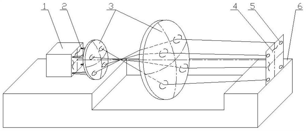
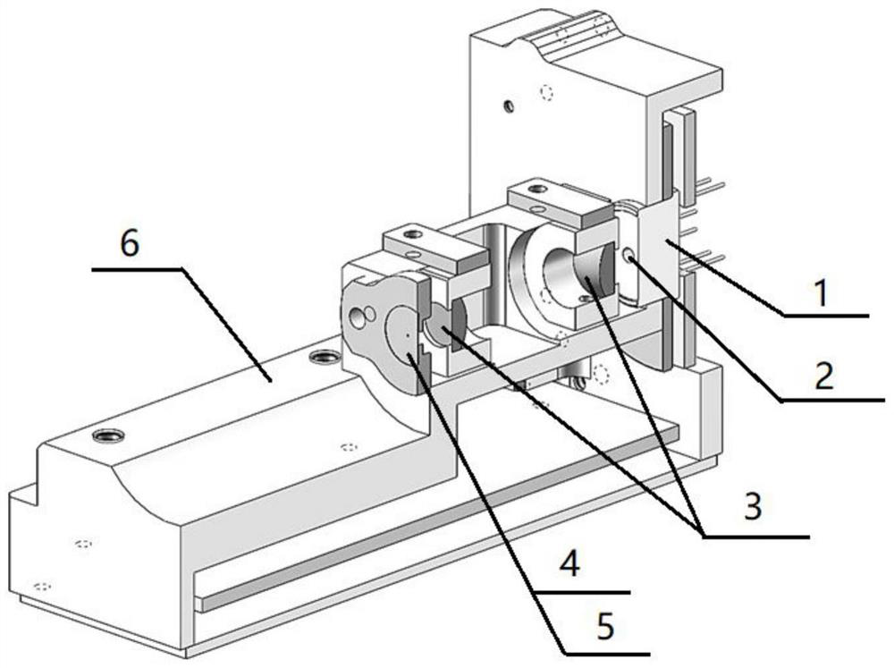
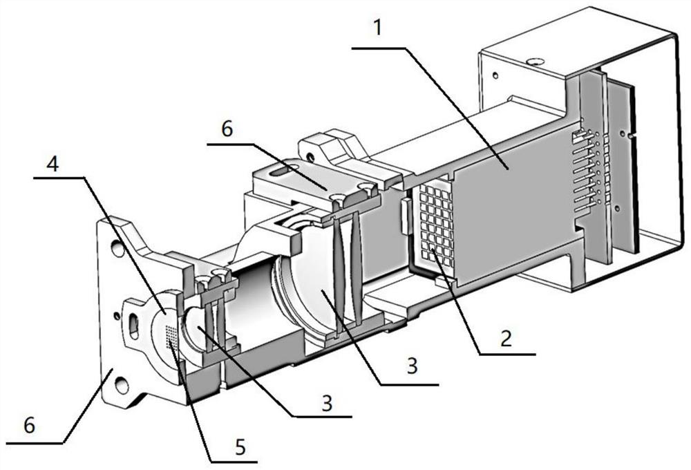
[0021] Reference Figures 1 through 3 As shown, the present embodiment integrates a photosensitive surface conjugated diaphragm detector optical machine assembly comprising a front-to-back coaxial arrangement of the diaphragm 4, projection optical system 3, detector 1, the photosensitive surface 2 on the detector 1 and the diaphragm 4 aperture 5, respectively, in the projection optical system 3 of the object and image surface, and according to the imaging relationship one-to-one correspondence.

[0022] Among them, the diaphragm 4, projection optical system 3, detector 1 are arranged on the installation structure 6, and the installation structure 6 is integrated and installed, and only the diaphragm hole 5 is open to the outside, whic...


PUM


Abstract

The invention discloses a detector optical machine assembly integrated with a photosensitive surface conjugate diaphragm, which is structurally characterized in that a photosensitive surface (2) of a detector (1) and a diaphragm aperture (5) of a diaphragm (4) are respectively positioned on an object surface and an image surface of a projection optical system (3) and are in one-to-one correspondence according to an imaging relationship. The detector (1), the projection optical system (3) and the diaphragm (4) are assembled on the same mounting structure (6) to form an integral optical machine assembly; the device is simple in structure, easy to install and adjust, accurate in object-image relation and firm and reliable in whole, the small hole can filter out adverse effects generated by external stray light, and the size of a detection area can be adjusted and the receiving view field of the photosensitive unit can be changed by configuring the sizes of the projection optics (3) and the diaphragm small hole (5) and system parameters; and the light source can be used as a receiving optical axis basis for the optical axis adjustment of the active photoelectric system, so that the subsequent complete machine adjustment is facilitated.

Description

Technical field [0001] The present invention belongs to the field of active lidar technology, relates to a detector optical machine assembly integrating a photosensitive surface conjugated diaphragm. Background [0002] Active photoelectric detection radar systems are mostly weak light signal detection, which has strict requirements for various types of noise suppression. When strong background light or close-range backscattered light is incident on the structure in the receiving optical path, it will produce a complex diffuse reflection stray light in the direction of propagation, and the stray light that is incident to the photosensitive surface will significantly reduce the signal-to-noise ratio of the received signal, and even cause the detector to be in saturation work, seriously interfering with the normal work of the detector. At present, in the single-cell laser ranging radar system, it is often set in the first image position of the receiving optical path to limit the re...

Claims


Application Information

Patent Timeline
IPC IPC(8): G01S7/481G01S17/08
CPCG01S7/481G01S17/08
Inventor 姜勇杨泽后陈永雄王楚吕明爱张国娟赵才曲张永科李少波
Owner SOUTH WEST INST OF TECHN PHYSICS
Why Eureka
Try Eureka