Differential amplification circuit, control method and signal amplification equipment

A differential amplifier circuit and controller technology, applied in the direction of differential amplifiers, amplifiers, DC-coupled DC amplifiers, etc., can solve the problems of increasing the complexity of the production process, large testing and adjustment costs, etc., to improve the common mode rejection ratio Effect

Pending Publication Date: 2022-05-27
SHANDONG UNIV
View PDF0 Cites 0 Cited by
  • Summary
  • Abstract
  • Description
  • Claims
  • Application Information

AI Technical Summary

Problems solved by technology

However, the inventors found that the process of laser trimming resistors brings relatively large testing and adjustment costs, and increases the complexity of the production process.

Method used


Image

  • Differential amplification circuit, control method and signal amplification equipment
  • Differential amplification circuit, control method and signal amplification equipment
  • Differential amplification circuit, control method and signal amplification equipment

Examples


Embodiment 1

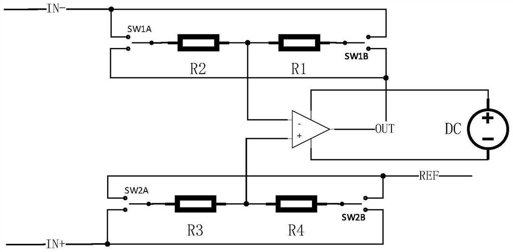
[0040] like figure 1 As shown, this embodiment provides a differential amplifier circuit, which includes an operational amplifier, a first resistor R1, a second resistor R2, a third resistor R3, a fourth resistor R4, a first switch SW1A, a second switch SW1B, The third switch SW2A and the fourth switch SW2B; wherein, the resistance values ​​of the first resistor R1 and the second resistor R2 are both within a first error range (for example: between -0.5 ohm and +0.5 ohm), the The resistance values ​​of the third resistor R3 and the fourth resistor R4 are both within the second error range (eg, between -0.4 ohm and +0.4 ohm); the first error range may also be the same as the second error range.

[0041] The first resistor R1 and the second resistor R2 are connected in series, and the connection point is connected to the negative input end of the operational amplifier; the other ends of the first resistor R1 and the second resistor R2 are respectively connected to the fixed end ...

Embodiment 2

[0049] This embodiment provides a control method for a differential amplifier circuit as described above, which includes:

[0050] The connected states of the first switch, the second switch, the third switch and the fourth switch are controlled so that the differential amplifier circuit is switched between the first state and the second state.

[0051] like image 3 As shown, in the first state, the first switch is connected to the output terminal of the operational amplifier, the second switch is connected to the negative pole of the input signal, the third switch is connected to the reference input terminal, and the fourth switch is connected to the positive pole of the input signal;

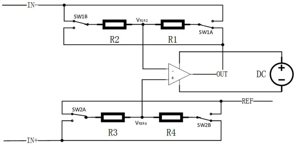
[0052] like Figure 4 As shown, in the second state, the first switch is connected to the negative terminal of the input signal, the second switch is connected to the output terminal of the operational amplifier, the third switch is connected to the positive terminal of the input signal, and...

Embodiment 3

[0076] This embodiment provides a signal amplifying device, which includes the differential amplifying circuit as described above.

[0077] Among them, signal amplification equipment such as instrumentation amplifier and so on.


PUM


Abstract

The invention provides a differential amplifier circuit, a control method and a signal amplification device. Wherein the differential amplification circuit comprises an operational amplifier, four resistors and four switches; the resistance values of the first resistor and the second resistor are within a first error range, and the resistance values of the third resistor and the fourth resistor are within a second error range; the first resistor and the second resistor are connected in series, and the connection point is connected with the negative input end of the operational amplifier; the other ends of the first resistor and the second resistor are correspondingly connected with the fixed ends of the first switch and the second switch respectively, the two movable ends of the first switch are correspondingly connected with the input signal cathode and the output end of the operational amplifier respectively, and the two movable ends of the second switch are correspondingly connected with the input signal cathode and the output end of the operational amplifier respectively; and the third resistor and the fourth resistor are symmetrically arranged with the first resistor and the second resistor. The output of the amplification circuit is the difference between the input signal positive voltage and the input signal negative voltage.

Description

technical field [0001] The invention belongs to the technical field of circuit design, and in particular relates to a differential amplifier circuit, a control method and a signal amplifier device. Background technique [0002] The statements in this section merely provide background information related to the present invention and do not necessarily constitute prior art. [0003] In an instrumentation amplifier, the differential amplifier circuit is the output stage of the instrumentation amplifier. In the existing differential amplifier circuit, in order to improve CMRR (Common Mode Rejection Ratio, common mode rejection ratio), the four resistors of the differential amplifier circuit must be precisely matched. Among them, a common configuration is that two resistors in a resistor pair have equal resistance values, for example, two resistor pairs composed of four resistors with the same resistance value. The real purpose of the resistor pair is to get the average of the ...

Claims


Application Information

Patent Timeline
Patent Type & Authority Applications(China)
IPC IPC(8): H03F1/56H03F3/45
CPCH03F1/56H03F3/45928
Inventor 李学勇徐定民
Owner SHANDONG UNIV
Why Eureka
Try Eureka