Distributed sample hold circuit for rail-to-rail input range

A distributed sampling and input range technology, applied in the electronic field, can solve the problems of limiting the input range of the pre-amplifier, reducing the bandwidth of the pre-amplifier, increasing power consumption and parasitic capacitance, etc.

Active Publication Date: 2012-07-25
无锡苏惠信息技术服务有限公司
View PDF3 Cites 5 Cited by
  • Summary
  • Abstract
  • Description
  • Claims
  • Application Information

AI Technical Summary

Problems solved by technology

In the CMOS process, the threshold voltage V of different process corners th The deviation and the existing lining offset effect directly limit the input range that the pre-amplifier can handle
Therefore, the gain, bandwidth, nonlinear transfer characteristics, random offset voltage, and input range of the pre-amplifier in the distributed sample-and-hold circuit become the ultimate limiting factors of the ADC performance
[0004] In order to solve the above problems in the distributed sample-and-hold circuit, literature [1] adopts the method of increasing the size of the input differential pair, reducing the offset voltage, improving the nonlinear transmission characteristics, and extending the input range, but at the cost of increasing power consumption and parasitic capacitance , thereby reducing the bandwidth of the pre-amplifier and limiting the conversion rate of the ADC
Literature [2] R Taft, C Menkus, MR Tursi, et al.A 1.8V 1.6GS/s 8b Self-Calibrating Folding ADC with 7.26ENOB at Nyquist Frequency[C].ISSCC2004, San Francisco, ...

Method used


Image

  • Distributed sample hold circuit for rail-to-rail input range
  • Distributed sample hold circuit for rail-to-rail input range
  • Distributed sample hold circuit for rail-to-rail input range

Examples


Embodiment Construction

[0020] The present invention is described in further detail below in conjunction with accompanying drawing:

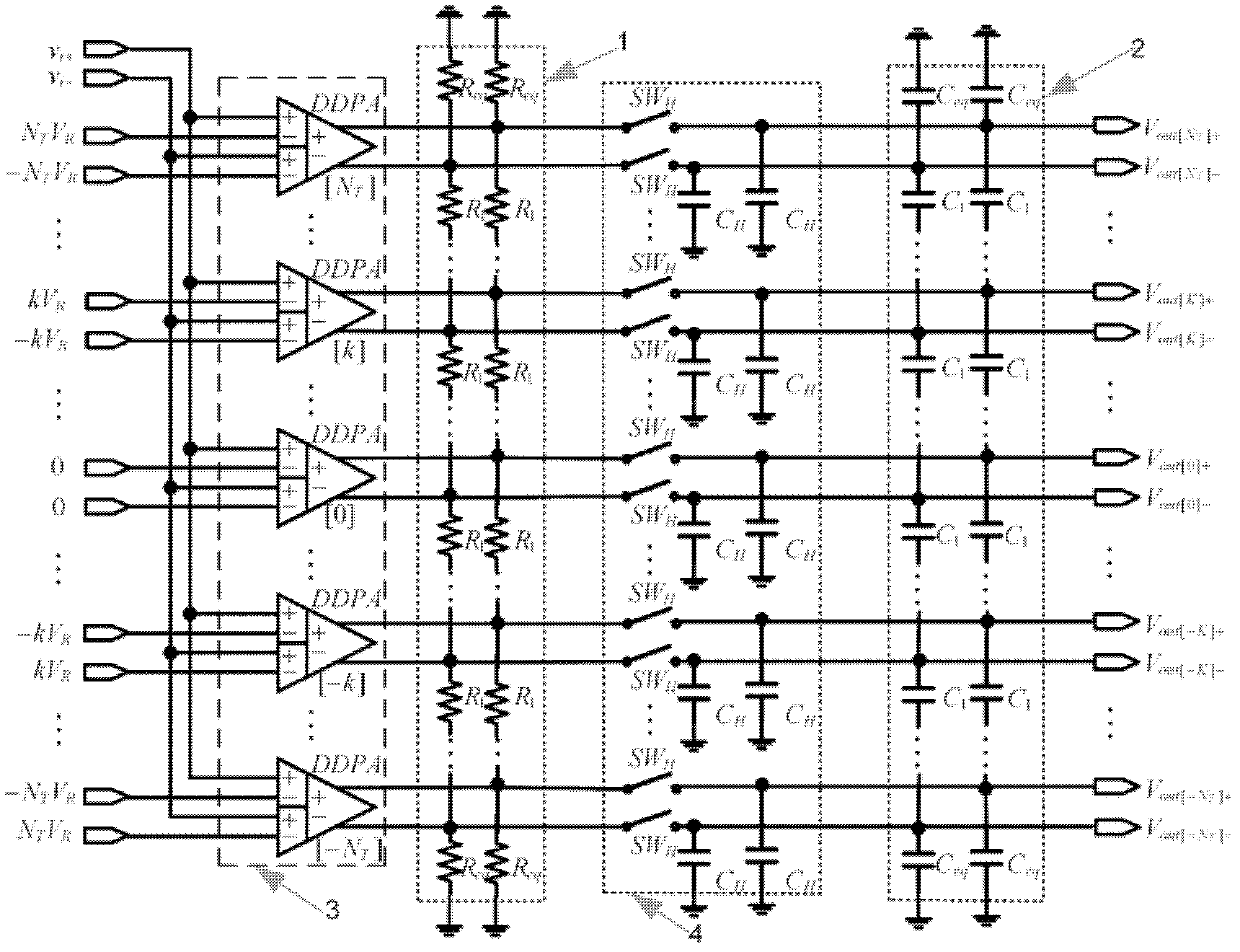
[0021] see figure 1 , the distributed sample-and-hold circuit of the rail-to-rail input range of the present invention includes a rail-to-rail differential differential pre-amplifier (DDPA) array, a resistance averaging network, a simple sample-holding array and a capacitor averaging network. The rail-to-rail differential differential preamplifier (DDPA) array consists of 2N T +1 identical DDPA, differential input signal v in+ , v in- They are respectively input to the non-inverting input terminal of the DDPA array (the input port is indicated by +), and the equally spaced differential reference voltage +N T V R ,-N T V R ,...,+KV R ,-KV R ,...,0,0,...,-KV R , +KV R ,...,-N T V R , +N T V R They are respectively input to the inverting input terminal of the DDPA array (input port represented by -). DDPA array at its maximum input range FS m By detecting ...


PUM


Abstract

The invention discloses a distributed sample hold circuit for the rail-to-rail input range, which comprises a rail-to-rail difference-differential preamplifier array, a resistance averaging network, a simple sample hold array and a capacitance averaging network. The rail-to-rail difference-differential preamplifier array comprises 2NT+1 identical rail-to-rail difference-differential preamplifiers, difference input signals vun+ and vin- are respectively inputted into a non-inverting input end of the rail-to-rail difference-differential preamplifier array, equally-spaced difference reference voltage +NTVR, -NTVR,..., +KVR, -KVR,..., 0, 0,..., -KVR, +KVR,..., -NTVR, +NTVR are respectively inputted to an inverting input end of the rail-to-rail difference-differential preamplifier array, and output of the rail-to-rail difference-differential preamplifier array and directly-connected nodes of resistance of the resistance averaging network are connected together to be inputted to a simple TH array. The distributed sample hold circuit for the rail-to-rail input range is high in speed and precision and good in common-mode rejection performance.

Description

Technical field: [0001] The invention belongs to the field of electronics, and relates to a sample-and-hold circuit widely used in folding interpolation ADCs (analog-to-digital converters), in particular to a distributed sample-and-hold circuit that uses a novel preamplifier structure to realize rail-to-rail input ranges circuit. Background technique: [0002] Sample and hold circuit is the key module of high-speed ADC. There are two types of sample-and-hold circuits for folding and interpolating ADCs: a single sample-and-hold circuit and a distributed sample-and-hold circuit. The proposal of a distributed sample-and-hold circuit alleviates the ADC's requirement that the sample-and-hold circuit maintain linearity over the entire input range. , in literature [1] Venes AGW, van de Plassche RJ.An 80-MHz, 80-mW, 8-b CMOS folding A / D converter with distributed track-and-hold preprocessing[J].IEEE Journal of Solid-State It was first proposed in Circuits, 1996, 31(12): 1846-1853,...

Claims


Application Information

Patent Timeline
IPC IPC(8): H03M1/54
CPCH03M1/54H03M1/1245H03M1/0646H03M1/0682H03M1/361
Inventor 邵志标张春茗
Owner 无锡苏惠信息技术服务有限公司
Why Eureka
Try Eureka