Silicon carbide micro-powder processing production device with intelligent proportioning function and method thereof
A silicon carbide micropowder and production device technology, applied to mixers with rotating stirring devices, chemical instruments and methods, carbon compounds, etc., can solve the problems of reducing production efficiency, cumbersome operation, and low efficiency of silicon carbide micropowder processing, and achieve Improve work efficiency, simple and fast operation, and convenient use
- Summary
- Abstract
- Description
- Claims
- Application Information
AI Technical Summary
Problems solved by technology
Method used
Image
Examples
Embodiment 1
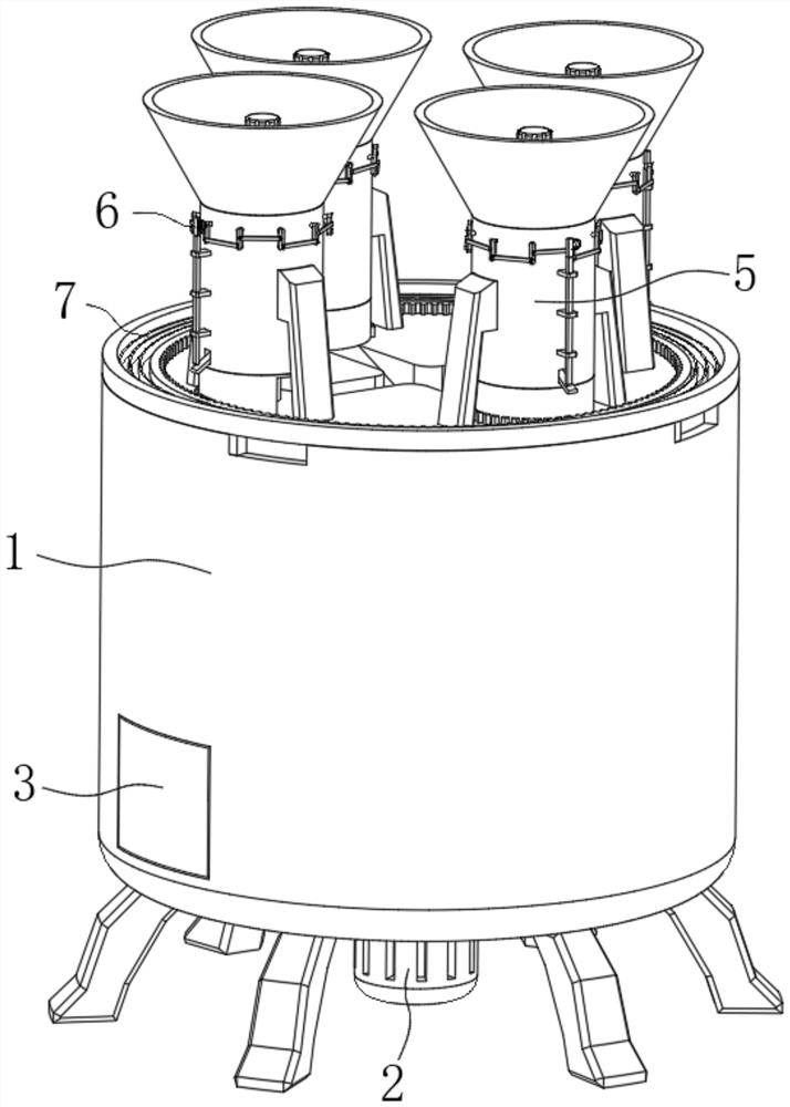
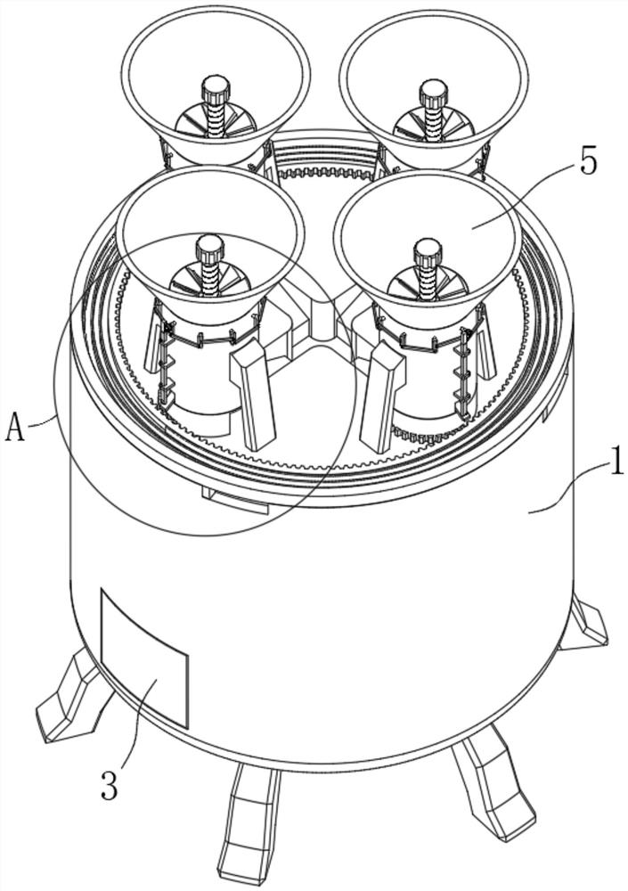
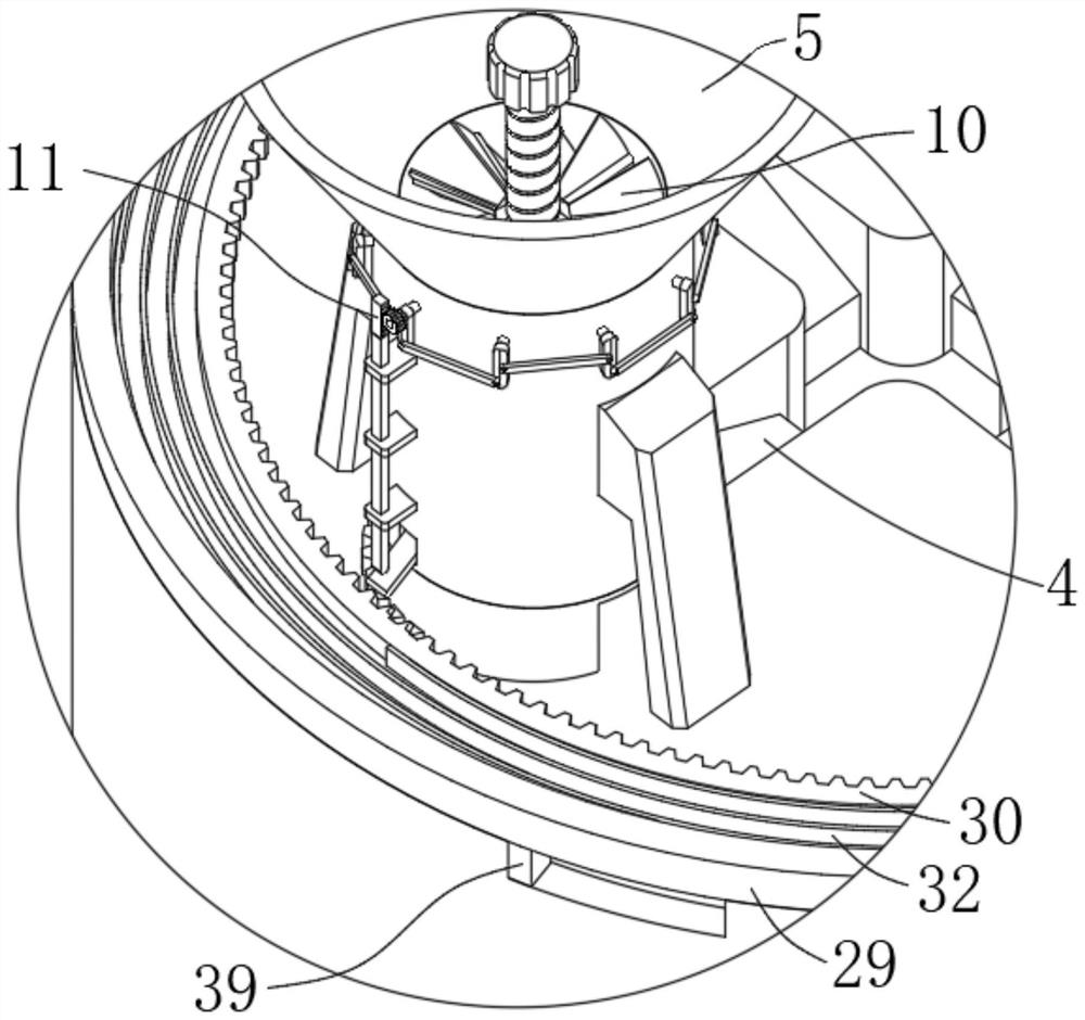
see Figure 1-Figure 3 , a silicon carbide micropowder processing and production device with intelligent proportioning function in the figure, including a body 1, a proportioning device 6 and a feeding device 7, the body 1 is provided with a stirring device 2, and the body 1 is provided with a box door 3. The top of the body 1 is provided with a feeding slot 4, and the top of the body 1 is fixedly connected with a plurality of feeding barrels 5 for storing different raw materials. The proportioning device 6 is installed in the feeding barrel 5 for taking out and setting The raw materials of the same weight are separated and stored, and the feeding device 7 is installed on the top of the machine body 1, which is used to link the part of the raw materials into the body 1 after the proportioning device 6 separates and stores a plurality of raw materials. 2 Stir and mix.
[0019] see Figure 2-Figure 3 and Figure 9, the proportioning device 6 in the figure includes a loading ba...
Embodiment 2
see Figure 5-Figure 6 The second embodiment will be described. This embodiment will further describe the first embodiment. The partition device 10 in the figure includes a fixed block 12 . The side surface of the fixed block 12 is rotatably connected with a plurality of rotating shafts 13 , and the rotating shafts 13 penetrate through the side of the feeding barrel 5 . The wall is rotatably connected with the feeding barrel 5, the rotating shaft 13 is fixedly connected with a fan-shaped baffle 14, one end of the rotating shaft 13 is fixedly connected with a vertical rod 15, and a connecting rod 16 is rotatably connected between the two adjacent vertical rods 15. The material barrel 5 is provided with a linkage 17 which is connected to the rotation of the rotating shaft 13 after the loading barrel 8 is loaded with the set material, so that the fan-shaped baffles 14 overlap each other to cut off the material above the material barrel 5 .
[0023] see Figure 5-Figure 9 , the li...
Embodiment 3
see Figure 5-Figure 9 Embodiment 3 will be described. This embodiment will further describe Embodiment 1. The feeding device 7 in the figure includes a rotating pipe 26 that is rotatably connected to the bottom surface of the feeding barrel 5. The rotating pipe 26 is provided with an opening 27. The top end is fixedly connected with an electromagnet 28 for adsorbing the bottom surface of the loading bucket 8, the top end of the body 1 is rotatably connected with a rotating ring 29 and a gear ring 30, and the side surface of the rotating tube 26 is provided with a half gear ring meshing with the gear ring 30. 31. The inner wall of the rotating ring 29 is fixedly connected with a clockwork spring 32 that is fixedly connected with the gear ring 30. The body 1 is provided with a mechanism for linking the rotating ring 29 to rotate when the loading bucket 8 is continuously loaded with raw materials, so that the clockwork spring 32 is charged. The rotating member 33 and the feeding ...
PUM
 Abstract
Description
Claims
Application Information
 - R&D
- Intellectual Property
- Life Sciences
- Materials
- Tech Scout
- Unparalleled Data Quality
- Higher Quality Content
- 60% Fewer Hallucinations
Browse by: Latest US Patents, China's latest patents, Technical Efficacy Thesaurus, Application Domain, Technology Topic, Popular Technical Reports.
© 2025 PatSnap. All rights reserved.Legal|Privacy policy|Modern Slavery Act Transparency Statement|Sitemap|About US| Contact US: help@patsnap.com


