Pipe stamping and cutting device for building construction based on notch control

A technology for building construction and truncation devices, which is applied in the directions of feeding devices, manufacturing tools, positioning devices, etc., can solve the problems of difficulty in accurately controlling the truncation position, cumbersome steps, etc., to achieve optimization effects, increase internal support force and static friction, The effect of increasing the tightening force and sealing

Active Publication Date: 2022-06-03
SHANDONG POLYTECHNIC COLLEGE
View PDF18 Cites 0 Cited by
  • Summary
  • Abstract
  • Description
  • Claims
  • Application Information

AI Technical Summary

Problems solved by technology

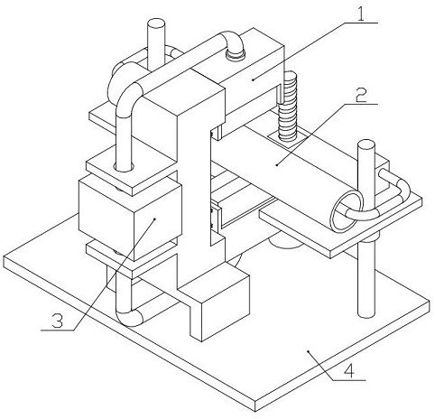
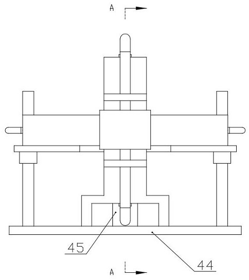
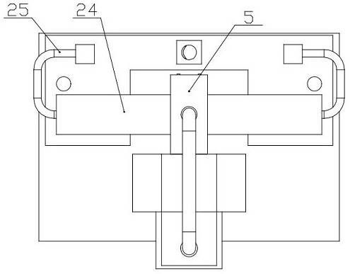
[0003] In view of the above situation, in order to overcome the defects of the prior art, the present invention proposes a pipe fitting that can be crushed by one operation, and the pipe fitting can be cut off in the middle of the flat area, and the position of the flat mouth can be adjusted independently, and the control A pipe punching cut-off device for building construction based on incision control of the arc-shaped bulge size; in order to solve the technical problems of the traditional pipe stamping cut-off process steps are cumbersome, and it is difficult to accurately control the cut-off position, the invention creatively proposes based on the principle of hydraulic and pneumatic transmission The fixed-point limit type external expansion type cutting mechanism is adopted. Without any hydraulic control valve, only through the ingenious hydraulic pressure and limit structure, the serial control of the two processes of stamping and cutting is realized.

Method used


Image

  • Pipe stamping and cutting device for building construction based on notch control
  • Pipe stamping and cutting device for building construction based on notch control
  • Pipe stamping and cutting device for building construction based on notch control

Examples


Embodiment Construction

[0020] The technical solutions in the embodiments of the present invention will be clearly and completely described below with reference to the accompanying drawings in the embodiments of the present invention. Obviously, the described embodiments are only a part of the embodiments of the present invention, rather than all the embodiments; based on the The embodiments of the present invention, and all other embodiments obtained by those of ordinary skill in the art without creative work, fall within the protection scope of the present invention.

[0021] In the description of the present invention, it should be understood that the terms "upper", "lower", "front", "rear", "left", "right", "top", "bottom", "inside", " “Outside” and other indications of orientation or positional relationship are based on the orientation or positional relationship shown in the accompanying drawings, which are only for the convenience of describing the present invention and simplifying the descripti...


PUM


Abstract

The invention belongs to the technical field of non-cutting machining, and particularly relates to a pipeline stamping and cutting device for building construction based on notch control. The invention discloses a pipeline stamping and cutting-off device for building construction based on notch control. The pipeline stamping and cutting-off device comprises a fixed-point limiting type external expansion type cutting-off mechanism, an internal jacking type bulge regulation and control mechanism, a hydraulic driving assembly and a lifting regulation mechanism. On the basis of the hydraulic and pneumatic transmission principle, a fixed-point limiting type external expansion type cut-off mechanism is creatively provided, and under the condition that no hydraulic control valve exists, serialization control over the two working procedures of stamping and cut-off is achieved only through an ingenious hydraulic and limiting structure; the invention further creatively provides an internal jacking type bulge regulation and control mechanism, the shape of the arc-shaped bulge is controlled, the sealing bowl opening can be automatically pre-tightened through internal pressure, and when the water pressure is increased, the pre-tightening force between the sealing bowl opening and the to-be-cut-off pipeline body can be adaptively increased to prevent the to-be-cut-off pipeline body from falling off along with the increase of the pre-tightening force between the sealing bowl opening and the to-be-cut-off pipeline body.

Description

technical field [0001] The invention belongs to the technical field of non-cutting processing, in particular to a punching and cutting device for pipelines used in building construction based on incision control. Background technique [0002] In the process of in-plant modular prefabrication and on-site construction of smart buildings, it is often necessary to flatten and truncate the pipe fittings to facilitate the use of structural supports and connection bolts. However, the traditional construction process has the following problems: A: Generally, two processes are required to be separated and operated independently. Therefore, it is very difficult to ensure that the truncation position is located in the center of the flattening area, and it is necessary to measure and mark when truncation; B: It is difficult to ensure that the flattened mouth after flattening is just on the diameter of the round tube; C: If the flat mouth after flattening is required to still be seal...

Claims


Application Information

Patent Timeline
Patent Type & Authority Applications(China)
IPC IPC(8): B21D28/28B21D43/00B21C51/00
CPCB21D28/28B21D43/003B21C51/00
Inventor 马素真张丽红孙贵杰
Owner SHANDONG POLYTECHNIC COLLEGE
Why Eureka
Try Eureka