High-temperature sputtering prevention protection device for numerical control machine tool and use method of high-temperature sputtering prevention protection device

A technology of numerical control machine tools and protective devices, applied in the field of numerical control machine tools, can solve the problems of reducing recycling efficiency, cooling and preventing sputtering of difficult workpieces, affecting the processing environment of workshops, etc., so as to reduce the demand for resources, improve the environmental protection effect, and avoid pungency effect of smell

Active Publication Date: 2022-06-03
QUZHOU UNIV
View PDF15 Cites 0 Cited by
  • Summary
  • Abstract
  • Description
  • Claims
  • Application Information

AI Technical Summary

Problems solved by technology

[0005] During machine tool processing, a large amount of iron filings will be generated, and the sputtered iron filings are likely to cause injury to the operator, and since the processing base is used to place the workpiece , its corners are vertical upwards, and its inner corners are at a 90-degree right angle. After cutting, splashed metal debris accumulates at the vertical corners. Usually, the workpiece is lowered by spraying coolant when mach

Method used


Image

  • High-temperature sputtering prevention protection device for numerical control machine tool and use method of high-temperature sputtering prevention protection device
  • High-temperature sputtering prevention protection device for numerical control machine tool and use method of high-temperature sputtering prevention protection device
  • High-temperature sputtering prevention protection device for numerical control machine tool and use method of high-temperature sputtering prevention protection device

Examples


Example Embodiment

[0034] The technical solutions in the embodiments of the present invention will be clearly and completely described below with reference to the accompanying drawings in the embodiments of the present invention. Obviously, the described embodiments are only a part of the embodiments of the present invention, but not all of the embodiments. Based on the embodiments of the present invention, all other embodiments obtained by those of ordinary skill in the art without creative efforts shall fall within the protection scope of the present invention.

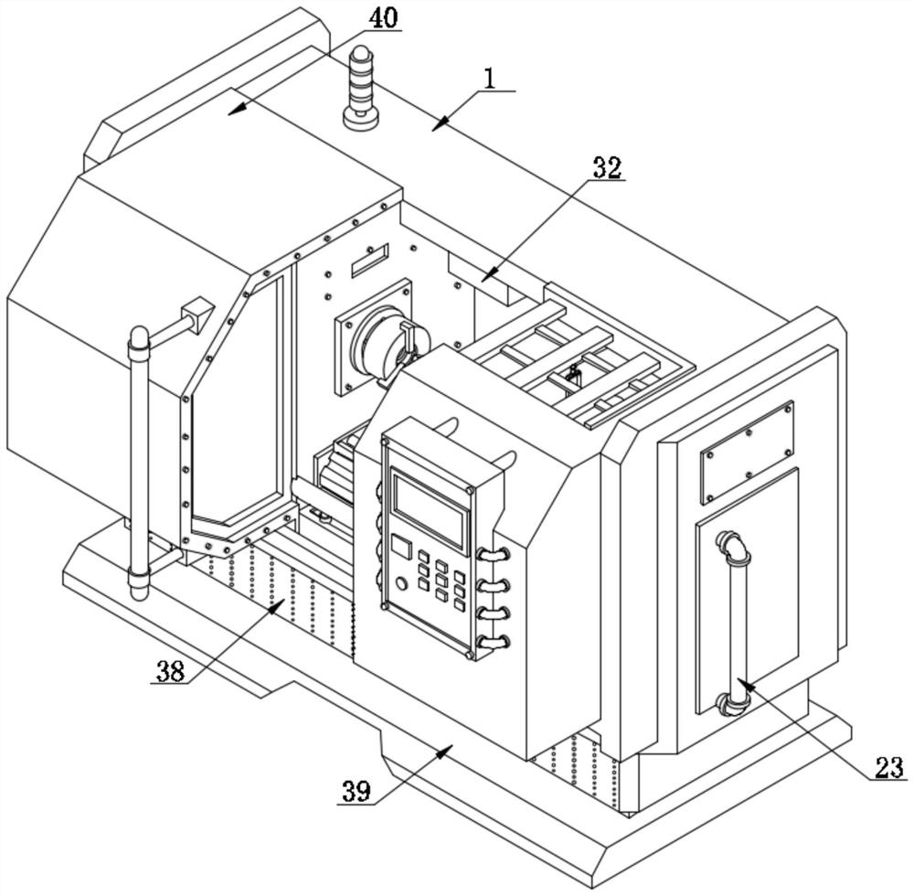
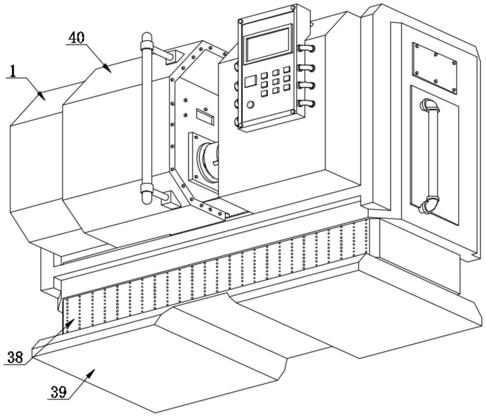
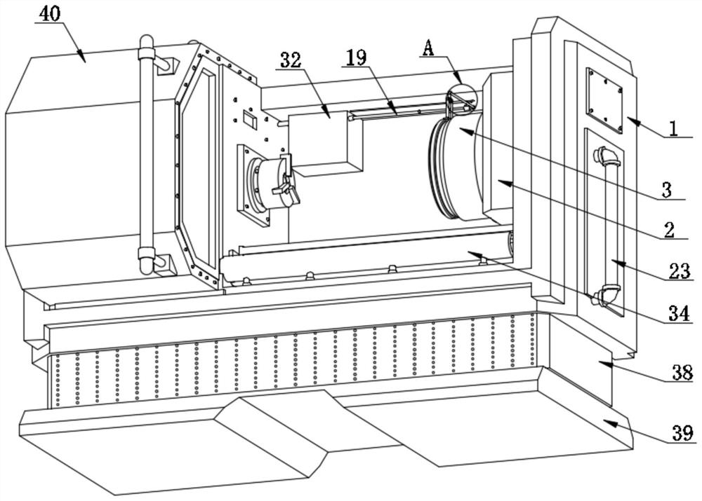
[0035] like Figure 1-8 As shown, the present invention provides a protective device for preventing high temperature sputtering for CNC machine tools, comprising a machine tool body 1, the right side of the inner wall of the machine tool body 1 is fixedly connected with the right side of the positioning frame 2, and the positioning frame 2 is fixedly connected inside There is an airtight cylinder 3, the inner wall of the airtight cyli...


PUM


Abstract

The invention discloses a high-temperature-sputtering-preventing protection device for a numerical control machine tool and a using method of the high-temperature-sputtering-preventing protection device, and particularly relates to the technical field of numerical control machine tools. The high-temperature-sputtering-preventing protection device comprises a machine tool body, and the right side face of the inner wall of the machine tool body is fixedly connected with the right side face of a positioning frame; the inner wall of the airtight cylinder is fixedly connected with the outer surface of a first sleeve, and a first guide groove is formed in the left side face of the first sleeve. Through the arrangement of the driving device, the centrifugal cylinder, the oil pump, the second sleeve and the spraying cylinder, the protection device can recycle cooling liquid while assisting in rapid heat dissipation of a workpiece during workpiece machining, the situation that the cooling liquid is in a high-temperature state for a long time is reduced, the cooling liquid can be treated in time, and the cooling efficiency is improved. The cooling liquid is prevented from generating pungent smell due to high-temperature volatilization, the environmental protection effect of the protection device is improved, meanwhile, the requirement of the protection device for resources is reduced, and compared with an existing protection device, a large amount of cost is saved.

Description

technical field [0001] The present invention relates to the technical field of numerical control machine tools, and more particularly, to a protective device for preventing high temperature sputtering for numerical control machine tools and a method of using the same. Background technique [0002] CNC machine tool is the abbreviation of digital control machine tool, which is an automatic machine tool equipped with a program control system. The control system can logically process the program specified by the control code or other symbolic instructions, decode it, represent it with coded numbers, and input it into the numerical control device through the information carrier. After arithmetic processing, various control signals are sent by the numerical control device to control the action of the machine tool, and the parts are automatically processed according to the shape and size required by the drawing. [0003] Machining parts on CNC machine tools mainly depends on the p...

Claims


Application Information

Patent Timeline
IPC IPC(8): B23Q11/00B23Q11/08B23Q11/10
CPCB23Q11/08B23Q11/0046B23Q11/0042B23Q11/10B23Q11/00B23Q11/1069Y02P70/10
Inventor 邓小雷林晓亮陈昱珅柳力豪方诚至丁志恒宋佳欣
Owner QUZHOU UNIV
Why Eureka
Try Eureka