Composite wing unmanned aerial vehicle automatic airport based on rotary clamping

A technology of unmanned aerial vehicles and composite wings, which is applied in the direction of motor vehicles, wing fan control mechanisms, unmanned aerial vehicles, etc., to solve the problem of insufficient endurance, avoid conductor heating, and reduce running time.

Active Publication Date: 2022-06-03
山东智航智能装备有限公司
View PDF7 Cites 3 Cited by
  • Summary
  • Abstract
  • Description
  • Claims
  • Application Information

AI Technical Summary

Problems solved by technology

[0005] In view of the deficiencies in the prior art, the purpose of the present invention is to provide a compound-wing UAV automatic airport based on rotary clamping, which solves the problem of interference and collision between the airborne equipment and the clamping centering mechanism or the nest body in the prior art. Risks and problems with inner compartment airtightness

Method used


Image

  • Composite wing unmanned aerial vehicle automatic airport based on rotary clamping
  • Composite wing unmanned aerial vehicle automatic airport based on rotary clamping
  • Composite wing unmanned aerial vehicle automatic airport based on rotary clamping

Examples


Embodiment 1

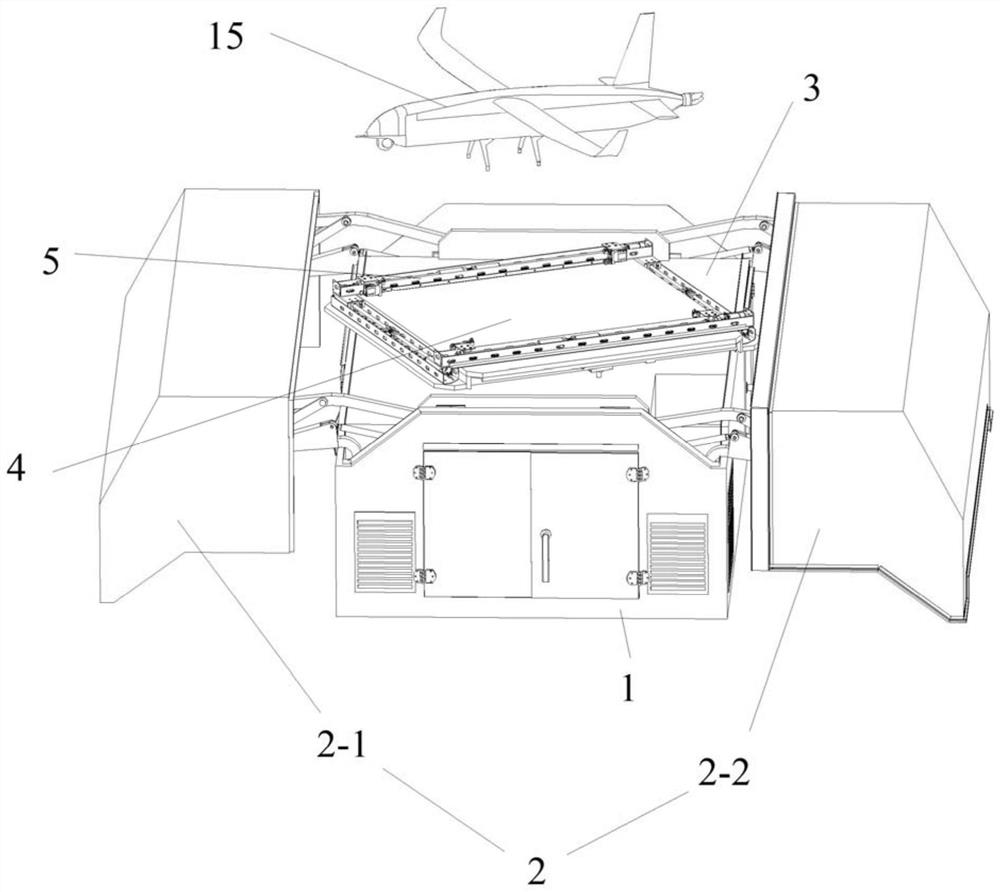
[0106] Follow the above technical solutions, such as Figure 1 to Figure 2As shown, a composite wing unmanned aerial vehicle automatic airport based on rotation and clamping includes a nest body 1 and an openable and closable nest cover 2 installed on the top of the nest body 1, and an inner cabin 3 is also installed in the nest body 1. , the height of the inner cabin 3 is the same as that of the nest 1, and a rotating platform 4 is also installed on the top of the inner cabin 3, and a clamping centering device 5 is installed on the rotating platform 4. The clamping centering device 5 A contact charging clamping device 6 is also installed thereon, and a wireless charging module 7 is installed under the rotating platform 4 .

[0107] The inner cabin 3 is a closed space to prevent external debris from entering the inner cabin 3 when the nest cover 2 is opened, and the rotating platform 4 is arranged outside the inner cabin 3;

[0108] The clamping and centering device 5 include...

Embodiment 2

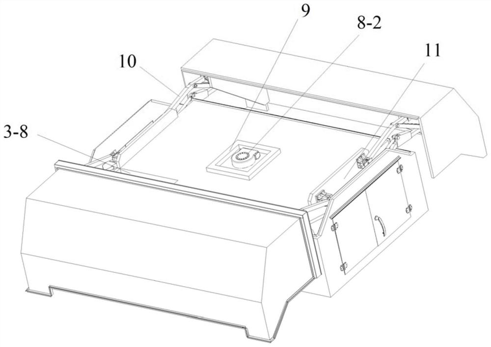
[0121] like Figure 3-6 As shown, the rotating platform 4 is connected with the nest 1 through the rotating mechanism 8;

[0122] The rotating mechanism 8 includes a rotating platform support base 8-1 installed on the bottom plate of the inner cabin 3 and a rotating support 8-2 installed at the top of the rotating platform support base 8-1; the rotating support 8-2 and the inner cabin 3 The interior is completely sealed, and the protection level of the rotating support 8-2 mechanism is not lower than IP66.

[0123] The rotating support 8-2 extends out of the inner cabin 3 through the opening of the top plate of the inner cabin 3, and the rotating platform 4 is connected with the rotating support 8-2. The rotating support 8-2 is used to drive the rotating platform 4 to rotate;

[0124] As a kind of preference of this embodiment:

[0125] The rotating platform 4 includes a platform base 4-1 and a parking pad 4-2 mounted on the top of the platform base 4-1;

[0126] A mountin...

Embodiment 3

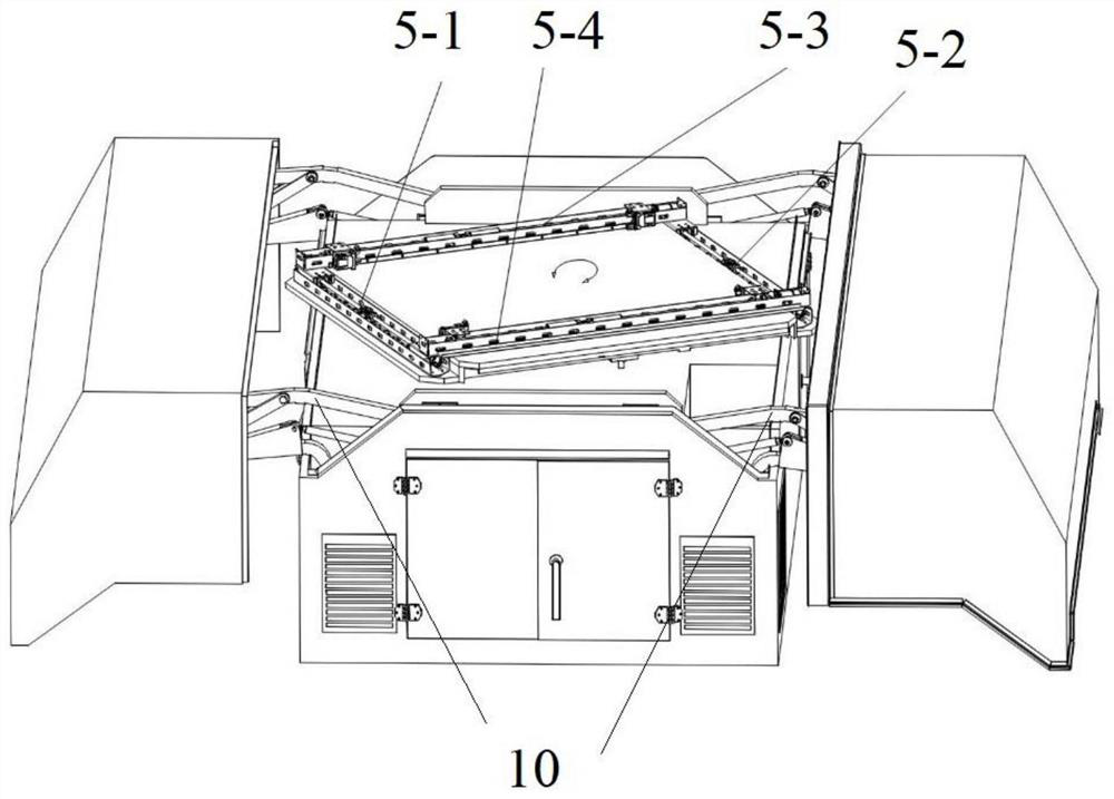
[0147] like Figure 7-10 As shown, the clamping and centering device 5 includes an X1 axis 5-1 and an X2 axis 5-2 connected with the rotating platform 4, and a Y1 axis 5-3 and a Y1 axis 5-3 connected with the X1 axis 5-1 and the X2 axis 5-2. Y2 axis 5-4;

[0148] The X1 axis 5-1 and the X2 axis 5-2 are respectively installed on the installation plane table 4-3, and the Y1 axis 5-3 and the Y2 axis 5-4 are arranged parallel to the X1 axis 5-1 and the X2 axis 5-2 above;

[0149] As a kind of preference of this embodiment:

[0150] The X1 axis 5-1 includes an X-axis base plate 5-1-1 connected to the installation plane table 4-3 and an X-axis side plate 5-1-1 vertically installed on both sides of the X-axis base plate 5-1-1 in the length direction. 2. A first X-axis transmission mechanism 5-1-3 and a second X-axis transmission mechanism 5-1-4 are installed in the length direction of the X-axis base plate 5-1-1;

[0151] The first X-axis transmission mechanism 5-1-3 includes an ...


PUM


Abstract

The invention discloses a composite wing unmanned aerial vehicle automatic airport based on rotary clamping. The composite wing unmanned aerial vehicle automatic airport comprises a nest body and a nest cover which is installed on the top of the nest body and can be opened and closed, an inner cabin is further installed in the nest body, a rotary platform is further installed on the top of the inner cabin, a clamping centering device is installed on the rotary platform, and a contact charging assembly is further installed on the clamping centering device. The clamping and centering device is installed above the rotating platform, the clamping and centering device and the rotating platform rotate together, the clamping and centering device can rotate along with the course of the unmanned aerial vehicle, the included angle between the clamping and centering device and an undercarriage is reduced when the unmanned aerial vehicle lands, and the unmanned aerial vehicle can be clamped to the designated position more easily and rapidly; the operation time of the clamping and centering device can be shortened, meanwhile, the single-time operation time of the automatic nest is shortened, the efficiency is improved, and the safety risk in the landing process of the unmanned aerial vehicle is avoided.

Description

technical field [0001] The invention relates to the technical field of unmanned aerial vehicles, in particular to a composite wing unmanned aerial vehicle automatic airport based on rotation and clamping. Background technique [0002] With the rapid development of UAV technology, UAVs have been widely used in power line inspection, oil pipeline inspection, border defense, coastal defense, traffic rescue, forest fire prevention and other fields. The composite wing UAV has the technical characteristics of large load and long endurance. It is suitable for flying missions in mountainous areas, deserts, islands and reefs that do not have the ability to build airports, but require heavy load and long flight time. However, when the above conditions are relatively harsh, the requirements for the use and maintenance of the UAV are higher. Therefore, in order to improve the UAV's ability to perform tasks, reduce the number of maintenance, and ensure the safe flight of UAVs, an autom...

Claims


Application Information

Patent Timeline
Patent Type & Authority Applications(China)
IPC IPC(8): B64F1/00B64F1/12B60L53/12B60L53/16E05F15/616E04H6/44
CPCB64F1/007B64F1/125B60L53/12B60L53/16E05F15/616E04H6/44B60L2200/10B64U80/00B64U50/19Y02T90/14Y02T10/70Y02T10/7072
Inventor 韩世刚焦鹏飞张欢飞蔡旭东贾旭东
Owner 山东智航智能装备有限公司
Why Eureka
Try Eureka