Novel planetary reduction gearbox
A planetary gearbox, a new type of technology, applied in the direction of the transmission box, components with teeth, belts/chains/gears, etc., can solve the problems of high machining accuracy, many parts of the planetary gearbox, and difficult processing. The effect of reducing the difficulty of processing, efficient transmission, and simple manufacturing
- Summary
- Abstract
- Description
- Claims
- Application Information
AI Technical Summary
Problems solved by technology
Method used
Image

Examples
Embodiment Construction
[0012] The present invention will be described in further detail below in conjunction with the embodiments.
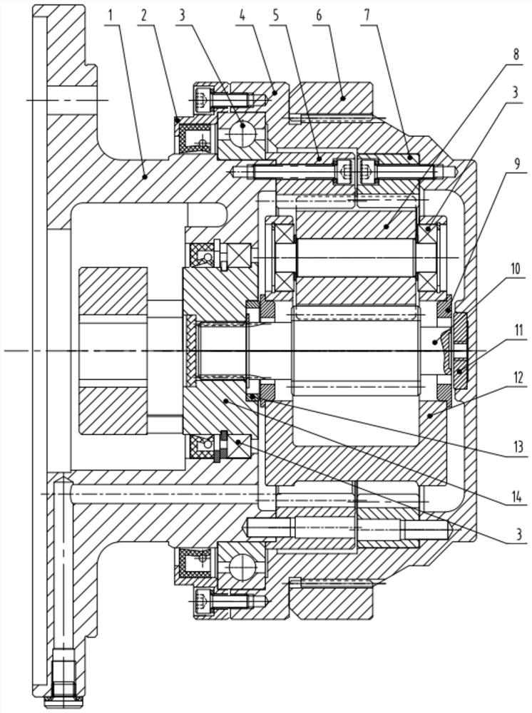
[0013] This embodiment proposes a new type of planetary reduction box, which is mainly used for hoisting structures or equipment in similar working conditions. like figure 1 As shown, it includes a fixed flange 1 and an output flange 4. The large end face of the fixed flange 1 is used for fixed connection with the motor casing of the hoisting mechanism, and the outer side of the small end face is connected to the output flange 4 through the bearing 3, so that the output flange 4 can be rotated relative to the fixed flange 1 .
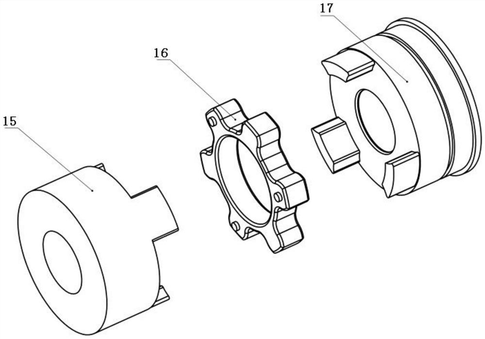
[0014] The fixed flange 1 is provided with a coupling 14. The coupling 14 in this embodiment adopts a claw coupling 14, including a motor end claw 15, an elastic block 16 and an input convex claw 17. The motor end convex claw 15 is used for In the fixed connection with the motor shaft of the hoisting mechanism, one side of the input pawl 17 is...
PUM
 Abstract
Description
Claims
Application Information