Directional well target depth design method

A design method and technology for directional wells, which are applied in the fields of seismology, instrumentation, climate sustainability, etc. for logging records, and can solve the problems of productivity reduction of unreachable reservoirs, errors between design depth and actual drilling depth, etc. To achieve the effect of widespread promotion, easy operation and good practicability

Pending Publication Date: 2022-06-03
CHINA PETROLEUM & CHEM CORP +1
View PDF0 Cites 0 Cited by
  • Summary
  • Abstract
  • Description
  • Claims
  • Application Information

AI Technical Summary

Problems solved by technology

[0006] The main purpose of the present invention is a method for designing the depth of the target point in a directional well. The method of the present invention can realize the accurate drilling of a new well designed to meet the target layer, so that the oil reservoir can be developed efficiently, and solve the problem caused by the error between the target point design depth and the actual drilling depth of a directional deviated well. Unable to drill reservoirs and reduced productivity

Method used


Image

  • Directional well target depth design method
  • Directional well target depth design method
  • Directional well target depth design method

Examples


Embodiment 1

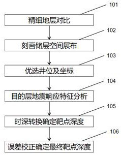
[0045] like figure 1 As shown, the directional well target depth design method includes the following steps:

[0046] Step 101, carry out a fine stratigraphic comparison study according to the completed directional well data, and confirm the corresponding relationship of sand bodies;

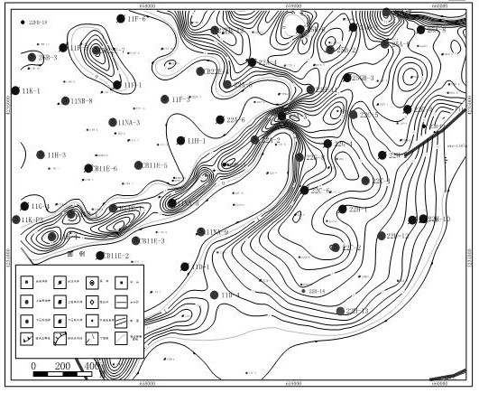
[0047]According to the drilled directional well data, combined with core observation, according to the vertical sedimentary cycle characteristics, combined with lithological and electrical characteristics, the target interval in the study area is divided into sand layers, and on this basis, the oil-bearing sand groups are divided into small layers. and the division of single sand bodies; use analytical laboratory and well logging data to analyze the development characteristics of the reservoir plane, clarify the provenance direction and law, and determine the corresponding relationship between sand bodies between wells.

[0048] Step 102: Determine the spatial distribution characteristics of th...

Embodiment 2

[0059] Taking Well 22H-13 as an example, the design method of the target depth of the directional well is described in detail. The steps are as follows:

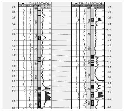
[0060] (1) According to the completed drilling data, combined with core observation, according to the vertical sedimentary cycle characteristics, combined with lithological and electrical characteristics, the target interval in the study area is divided into sand layers, and on this basis, the oil-bearing sand groups are divided into small layers and the division of single sand bodies. At the same time, the completion drilling analysis, testing, logging and other data are used to confirm the corresponding relationship between sand bodies in the target layer. The comparison chart of each layer is as figure 2 shown.

[0061] (2) According to the lithology data of the completed well core, analyze the physical properties of the test, the logging curve and the oil-bearing characteristics, interpret the effective thickness of t...


PUM


Abstract

The invention belongs to the technical field of oilfield development, and relates to a directional well target depth design method. Comprising the following steps that 1, fine stratigraphic comparison is conducted, and a sand body corresponding relation is obtained; 2, depicting reservoir spatial distribution, and determining spatial distribution characteristics of a target sand body; 3, well positions and coordinates are optimized; 4, synthetic record seismic calibration is conducted on the drilled directional well, and seismic response feature analysis is conducted on a target stratum; step 5, performing time-depth conversion to determine the depth of the target spot; and 6, calculating the error between the time conversion depth of the well drilling target and the actual drilling depth, and correcting the converted depth of the new well by taking the error as a correction value, so as to obtain the target depth of the new directional well. The method solves the problems of high water content rising speed, geological reserve loss and the like caused by the influence of non-uniform well spacing, low depth and the like due to the depth deviation of the target spot of the directional well, and can be widely popularized and applied.

Description

technical field [0001] The invention belongs to the technical field of oilfield development, and relates to a method for designing the depth of a directional well target point. Background technique [0002] With the improvement of the country's environmental protection requirements, the increasingly complex surface conditions and the mass production of offshore oilfields, directional wells have become one of the important means of efficient oilfield development at this stage. The use of directional well technology can make oil and gas resources with limited surface and underground conditions, especially offshore oil fields, economically and effectively developed, which can greatly increase oil and gas production and reduce drilling costs, which is conducive to protecting the natural environment, and has significant economic and economic benefits. social benefit. [0003] In the process of directional well trajectory measurement, there are many factors that may cause traject...

Claims


Application Information

Patent Timeline
Patent Type & Authority Applications(China)
IPC IPC(8): G01V1/50
CPCG01V1/50G01V2210/6169Y02A90/30
Inventor 李健杜玉山崔晴晴张海娜张强翟亮王志伟张鹏刘敏胡晨彬
Owner CHINA PETROLEUM & CHEM CORP
Why Eureka
Try Eureka