Machine tool protective cover unit sheet metal machining equipment

A technology of unit sheet metal and processing equipment, applied in the field of sheet metal stamping processing, can solve the problems affecting the efficiency of steel plate stamping, the deviation of raw material steel plates, and the easy damage of steel plates, so as to improve the replacement speed, ensure stability, and protect the shape. Effect

Pending Publication Date: 2022-06-07
徐州艾奇川自动化设备有限公司
View PDF0 Cites 4 Cited by
  • Summary
  • Abstract
  • Description
  • Claims
  • Application Information

AI Technical Summary

Problems solved by technology

[0004] The existing sheet metal processing of machine tool shields mainly uses punching machines to stamp prefabricated block steel plates so that they can be stamped into specific shapes, and then assemble the stamped steel plates in order from large to small. Finally, the machine tool protective cover is made. The existing machine tool protective cover is simple to process, but there are the following problems: 1. During the processing of the existing machine tool protective cover, the raw material steel plate is prone to offset, resulting in the appearance of the processed steel plate. asymmetrical case
[0005] 2. During the processing of the existing machine tool protective cover, the steel plate is attached to the mold of the stamping machine, and it is difficult to take it out, which greatly affects the efficiency of steel plate stamping, and the steel plate is divided by cutting before stamping It is formed into multiple plate-shaped steel plates, so the iron filings generated during cutting are adsorbed on the surface of the steel plate, and when it is stamped again, the surface of the steel plate is prone to damage

Method used


Image

  • Machine tool protective cover unit sheet metal machining equipment
  • Machine tool protective cover unit sheet metal machining equipment
  • Machine tool protective cover unit sheet metal machining equipment

Examples


Embodiment Construction

[0034] The technical solutions in the embodiments of the present invention will be clearly and completely described below with reference to the accompanying drawings in the embodiments of the present invention. Obviously, the described embodiments are only a part of the embodiments of the present invention, but not all of the embodiments. Based on the embodiments of the present invention, all other embodiments obtained by those of ordinary skill in the art without creative efforts shall fall within the protection scope of the present invention.

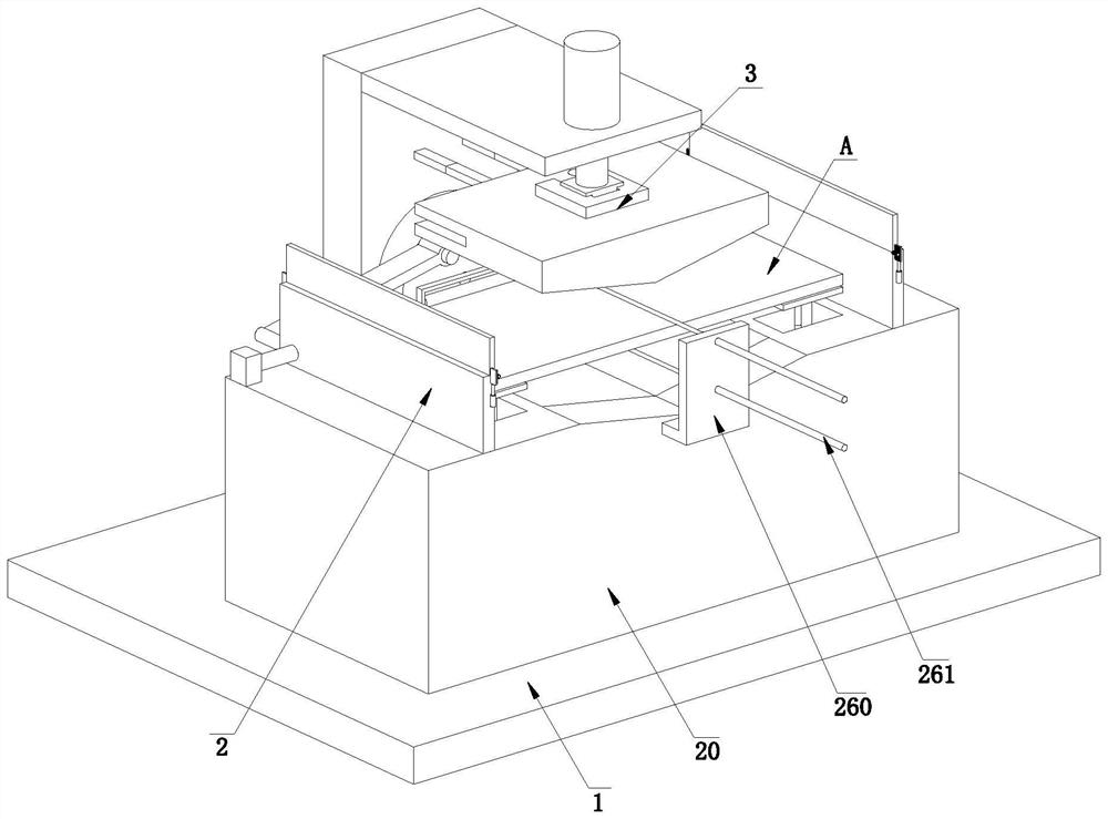
[0035] see figure 1 , a machine tool protective cover unit sheet metal processing equipment, including a base plate 1, a fixing device 2 and a punching device 3, the base plate 1 is fixedly installed with a fixing device 2, a punching device 3 is installed on the base plate 1, and the punching device 3 is located in the fixed position Above the device 2, when working, the operator first places the steel plate A to be punched on the fi...


PUM


Abstract

The invention provides machine tool protective cover unit sheet metal machining equipment, and relates to the technical field of sheet metal stamping machining, the machine tool protective cover unit sheet metal machining equipment comprises a bottom plate, a fixing device and a stamping device, the fixing device is fixedly installed on the bottom plate, the stamping device is installed on the bottom plate, and the stamping device is located above the fixing device; in addition, the machine tool protective cover can solve the problems that in the machining process of an existing machine tool protective cover, a raw material steel plate of the machine tool protective cover is prone to deviation, and consequently the machined steel plate is asymmetric; 2, in the machining process of an existing machine tool protective cover, a steel plate is attached to a die of a punching machine and is difficult to take out, so that the punching efficiency of the steel plate is greatly influenced, the steel plate is cut into a plurality of plate-shaped steel plates in a cutting mode before being punched, scrap iron generated in the cutting process is adsorbed to the surface of the steel plate, and the punching efficiency of the steel plate is influenced. And when the steel plate is punched, the surface of the steel plate is easy to damage.

Description

technical field [0001] The invention relates to the technical field of sheet metal stamping processing, and specifically provides a sheet metal processing equipment for a machine tool protective cover unit. Background technique [0002] The machine tool protective cover is a very important part of the machine tool. It is mainly used to protect the guide rail of the machine tool and avoid the corrosion and damage of some tight parts inside the machine tool. At the same time, when the machine tool is working, the machine tool protective cover can be timely. In order to prevent the debris generated by the chips from splashing at will, the role of the machine tool guard is particularly important. [0003] The machine tool protective cover adopts a telescopic structure, and the machine tool protective cover is extended and shortened by the operator's pulling and pulling, so the processing of the machine tool protective cover also increases a certain degree of difficulty. Process...

Claims


Application Information

Patent Timeline
Patent Type & Authority Applications(China)
IPC IPC(8): B21D5/02B21D43/00B21D45/02B21D37/04B08B1/00
CPCB21D5/02B21D5/0254B21D5/002B21D45/02B21D37/04B08B1/008Y02P70/10
Inventor 闫飞飞
Owner 徐州艾奇川自动化设备有限公司
Why Eureka
Try Eureka