Direct-current servo motor with good magnetic field pushing coherence
A DC servo and coherent technology, applied in the direction of shielding electromagnetic fields, electromechanical devices, structural connections, etc., can solve the weight increase of DC servo motors, the impact of vibration of servo motors, and the continuity that affects the stability of DC servo motor rotation, etc. problem, achieve the effect of reducing weight and strengthening stability
- Summary
- Abstract
- Description
- Claims
- Application Information
AI Technical Summary
Problems solved by technology
Method used
Image
Examples
Embodiment 1
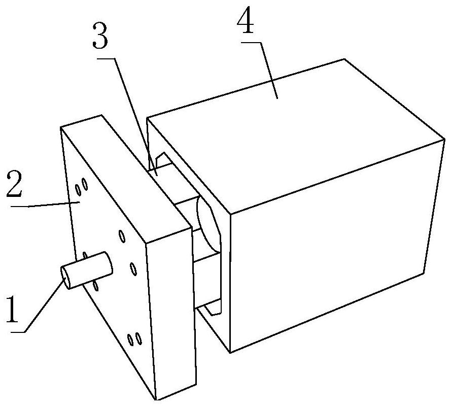
[0032] like Figure 1-5 As shown, the present invention provides a DC servo motor with good magnetic field driving coherence, including a DC servo motor body 1, a vibration damping box mechanism 2 is movably connected to the left side of the DC servo motor body 1, and the vibration damping box mechanism 2 includes a spring Two 26, one end of the spring two 26 is fixedly connected with the box shell 21, the outer surface of the DC servo motor body 1 is fixedly mounted with a motor housing mechanism 3, the motor housing mechanism 3 includes a hexagonal cylinder mechanism 33, a hexagonal cylinder mechanism 33 includes a hexagonal ring 331 , a magnetic field attenuation mechanism 4 is movably connected to the outside of the DC servo motor body 1 , and the magnetic field attenuation mechanism 4 includes an iron-nickel and alloy frame 43 , and an iron-nickel alloy strip 42 is fixedly connected to the inside of the iron-nickel and alloy frame 43 .
[0033] In this embodiment, the vib...
Embodiment 2
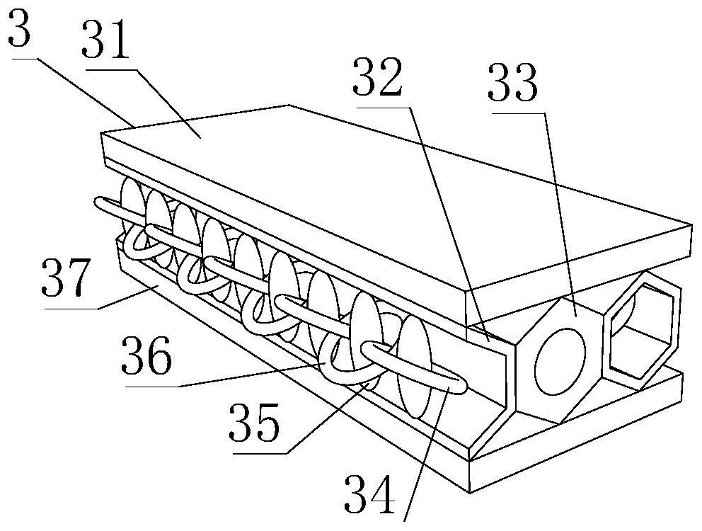
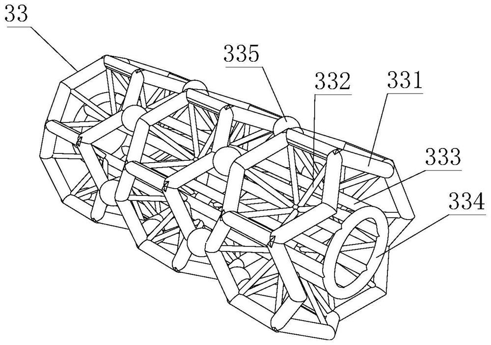
[0035] like Figure 1-5 As shown, on the basis of Embodiment 1, the present invention provides a technical solution: preferably, the inner side of the hexagonal ring 331 is fixedly connected with a connecting rod 332, and the other end of the connecting rod 332 is fixedly connected with a fixed rod 333, and the fixed rod 333 The two ends of the hexagonal ring 331 are fixedly connected with a fixing ring 334, the outer side of the hexagonal ring 331 is fixedly connected with a spherical connecting body 335, the upper side of the hexagonal cylinder mechanism 33 is fixedly connected with a plastic plate 1 31, and the lower side of the hexagonal cylinder mechanism 33 is fixedly connected. There is a second plastic plate 37, one side of the hexagonal cylinder mechanism 33 is fixedly connected with a hexagonal ring column 32, the upper side of the hexagonal ring column 32 is fixedly connected with the lower side of the plastic plate one 31, and the lower side of the hexagonal ring co...
Embodiment 3
[0038] like Figure 1-5 As shown, on the basis of Embodiment 1, the present invention provides a technical solution: preferably, an aluminum strip 44 is fixedly connected to the inner side of the iron-nickel and alloy frame 43, and an iron plate 45 is fixedly connected to the other side of the aluminum strip 44. , the inner side of the iron plate 45 is fixedly connected with the plastic shell 41, the top surface of the inner cavity of the plastic shell 41 is fixedly connected with the outer surface of the iron-nickel alloy strip 42 and the outer surface of the iron-nickel and alloy frame 43, the plastic shell 41 An insulating layer 46 is fixedly connected to the side surface, and a sponge layer 47 is fixedly connected to the inner side of the insulating layer 46 .
[0039] In this embodiment, the magnetic field attenuation mechanism 4 is covered on the outside of the DC servo motor body 1, so that the sponge layer 47 is closely attached to the outer surface of the DC servo mot...
PUM
 Abstract
Description
Claims
Application Information
 - R&D
- Intellectual Property
- Life Sciences
- Materials
- Tech Scout
- Unparalleled Data Quality
- Higher Quality Content
- 60% Fewer Hallucinations
Browse by: Latest US Patents, China's latest patents, Technical Efficacy Thesaurus, Application Domain, Technology Topic, Popular Technical Reports.
© 2025 PatSnap. All rights reserved.Legal|Privacy policy|Modern Slavery Act Transparency Statement|Sitemap|About US| Contact US: help@patsnap.com


