Limb traction device for burn department operation

A traction device and a technique for surgery, which are applied in the field of limb traction devices used in burn surgery, can solve the problems of medical staff affecting limb traction, deterioration of burn parts, secondary injury, etc., and achieve convenient bandaging, enlarge the surgical field, and avoid injury. Effect

Inactive Publication Date: 2022-06-21
AFFILIATED HOSPITAL OF NANTONG UNIV
View PDF0 Cites 0 Cited by
  • Summary
  • Abstract
  • Description
  • Claims
  • Application Information

AI Technical Summary

Problems solved by technology

[0002] When operating on a burn patient in the burn department of a hospital, in order to facilitate the doctor to perform the operation, it is usually necessary to lift the patient's limbs, so as to keep the patient's limbs away from the surgical site, or to facilitate surgery on the limbs, while the traditional traction method is The patient's limbs are directly lifted by the medical staff. However, with the long-term operation, the physical strength of the medical staff may affect the traction of the limbs. Therefore, in order to save effort, most of them are tied to the patient's limbs by straps at present. Then lift and pull the patient's limbs in a large shape to achieve the purpose of limb traction
[0003] However, although this traction method can avoid medical personnel from manually lifting the traction, it is easy to cause a large pull on the patient's limbs at the joint of the straps under long-term traction, thereby causing the limbs to be damaged. If the burned part is on the limb, it will even aggravate the deterioration of the burned part and cause secondary damage

Method used


Image

  • Limb traction device for burn department operation
  • Limb traction device for burn department operation
  • Limb traction device for burn department operation

Examples


Embodiment 1

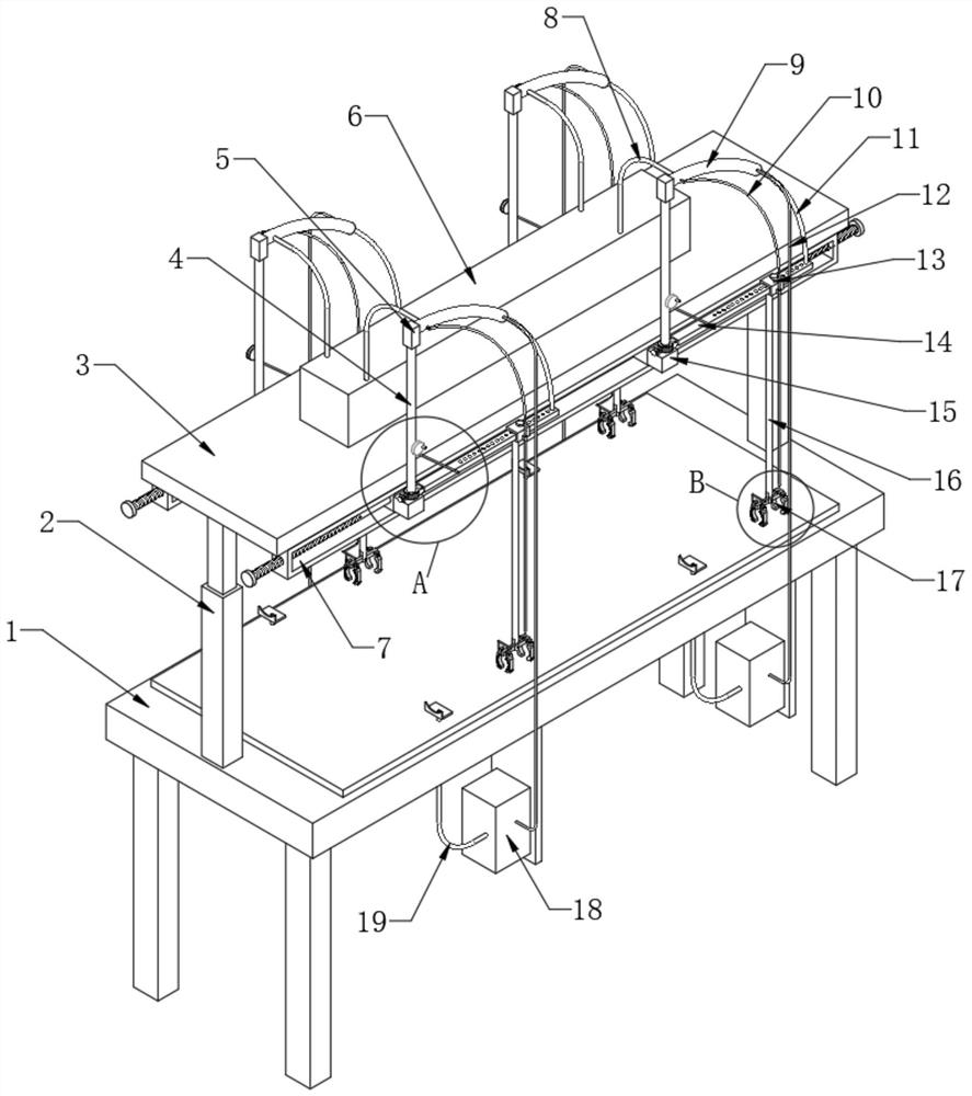
[0029] Example 1: Before the operation, the burn patient is placed on the operating table 1. The operating table 1 is covered with soft pads. The two sets of traction mechanisms correspond to the patient's arms and legs respectively, and then the traction components correspond to the arms or legs one by one.

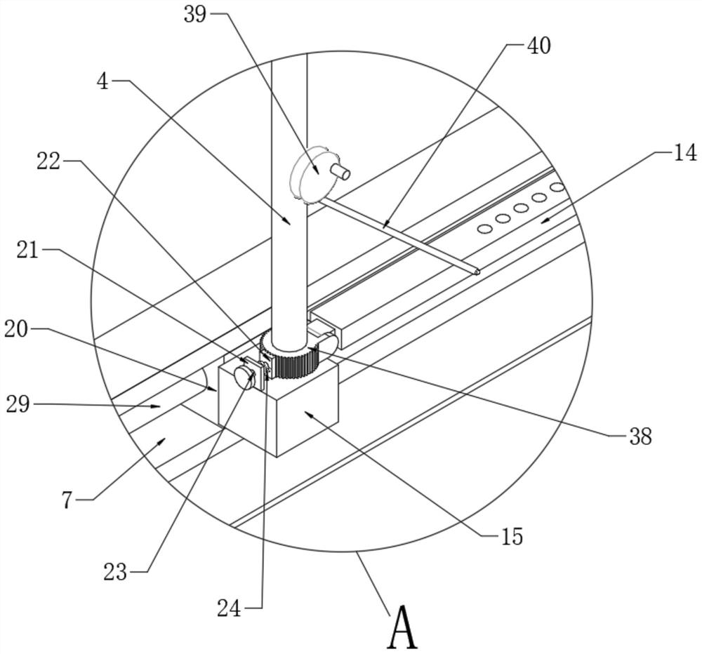
[0030] Then, when the limb of the burn patient needs to be pulled, first adjust the mounting block 15 corresponding to the limb to be pulled in the horizontal direction through the external structure, so that the position of the mounting block 15 is the same as that of the patient's shoulder or crotch and other arms or legs. The parts that rotate around the axis are on the same vertical line.

[0031] Then, the vertical rod 4 is adjusted by an external mechanism, so that the installation rod 14 is in a parallel state with the patient's arm or leg.

[0032] After adjustment, the adjustment block 13 is adjusted by an external mechanism, and the adjustment block 13 is adjus...

Embodiment 2

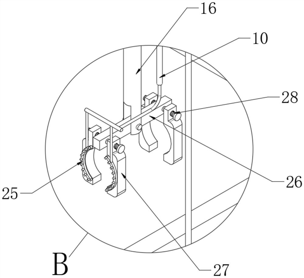
[0039] Embodiment 2, based on Embodiment 1, can refer to figure 1 , Figure 4 and Figure 5 , the inner cavity of the arc-shaped piston tube 9 between the piston block 32 and the fixed block 5 is set as the liquid cavity 33. When the installation rod 14 is lifted up and pulled, it will drive the arc-shaped piston rod 11 and the piston block 32 along the arc The inner wall of the shaped piston tube 9 moves, and the disinfectant in the liquid chamber 33 is squeezed out through the liquid outlet pipe 10 and sprayed out through the nozzle 25. Since the nozzle 25 is installed on the binding member 17, the sprayed disinfectant will spray onto the limb of the patient, thereby disinfecting the limb.

[0040] If it is a limb burn, the surface of the limb can be sterilized at the same time as preoperative traction, and then due to the traction of the limb, the limb will play the role of drainage, so that the disinfected disinfectant will flow down the limb to avoid confusion. Splash ...

Embodiment 3

[0043] Embodiment 3, based on Embodiment 2, can refer to figure 1 , Figure 4 and Figure 5 , the inner cavity of the arc-shaped piston tube 9 between the piston block 32 and the arc-shaped piston rod 11 is set as the air cavity 34. Before pulling the limb, first clamp the corresponding card 31 under the patient's limb, and then when the piston block 32 When the disinfectant in the liquid chamber 33 is squeezed out through the nozzle 25, the air chamber 34 will generate a negative pressure with the movement of the piston block 32, and then a negative pressure will be generated in the liquid collecting tank 18 through the ventilation pipe 12, so that the patient can be discharged from the air chamber 34. The mixed solution of disinfectant and pus drained from the limbs will flow into the splices 30, and then sucked into the collecting tank 18 through the suction pipe 19 to complete the collection of the mixed solution.

[0044] By setting the inner diameter of the ventilation...


PUM


Abstract

The limb traction device comprises an operating table, a top plate is fixed to the top of the operating table through a supporting rod, and two traction structures are arranged at the bottom of the top plate; the traction mechanism comprises two traction assemblies, each traction assembly comprises a mounting block capable of being slidably adjusted in the horizontal direction, a vertical rod capable of being rotationally adjusted along the axis is rotationally installed at the top of each mounting block, and a mounting rod capable of being rotationally adjusted in the vertical direction is installed on the outer wall of each vertical rod. The outer wall, away from the mounting block, of the mounting rod is provided with an adjusting block capable of sliding along the outer wall of the mounting rod for adjustment, and the bottom of the adjusting block is rotationally connected with a vertical connecting rod. Through cooperation of the structures, pulling on the skin of the arms or the legs of a patient can be reduced, hurt to the skin of the arms or the legs of the patient due to a long-time operation can be avoided, and if limbs are burnt, secondary hurt to the limbs can be avoided.

Description

technical field [0001] The invention relates to the technical field of traction devices, in particular to a limb traction device for burn surgery. Background technique [0002] When operating on burn patients in the hospital's burn department, in order to facilitate the operation of the doctor, the patient's limb usually needs to be lifted, so as to keep the patient's limb away from the surgical site, or to facilitate the operation on the limb. The traditional traction method is The patient's limb is directly lifted by the medical staff. However, with the long-term operation, the physical strength of the medical staff may affect the traction of the limb. Therefore, in order to save effort, most of the patients are tied to the patient's limb with a bandage. Then, the patient's limbs are lifted and pulled in a large shape to achieve the purpose of limb traction. [0003] However, although this traction method can avoid the manual lifting of the traction by the medical staff, ...

Claims


Application Information

Patent Timeline
Patent Type & Authority Applications(China)
IPC IPC(8): A61G13/12A61G13/10
CPCA61G13/1235A61G13/1245A61G13/102
Inventor 姚望望吴杨炀曹玲张逸
Owner AFFILIATED HOSPITAL OF NANTONG UNIV
Why Eureka
Try Eureka