

Intelligent cross rod pressure welding equipment integrating feeding, machining and discharging and working method
A technology of crossbar and equipment, applied in the field of intelligent crossbar pressure welding equipment, can solve the problems of increasing equipment cost, consuming a lot of manpower and time, and consuming a lot of manpower and material resources, so as to reduce manual labor and improve production efficiency. , the effect of improving stability
Pending Publication Date: 2022-06-21
苏州鹄珂智能科技有限公司
View PDF0 Cites 2 Cited by
- Summary
- Abstract
- Description
- Claims
- Application Information
AI Technical Summary
Problems solved by technology
Most of the existing transmission mechanisms are transmitted by transmission rollers or conveyor belts. Not only is the structure relatively complex, but also because both the transmission rollers and the conveyor belts require continuity, which increases the investment in equipment costs. ;
Moreover, due to the characteristics of the flat steel structure, it will be offset during transportation, and even two adjacent flat steels will stick together, which will not only bring a lot of inconvenience to the subsequent processing, but also affect the quality of the product. The processing quality is affected, so many existing processing equipment need to manually correct the position of the flat steel, which not only requires a lot of manpower and time;
At the same time, in the process of steel grating processing, the flat steel is transported to the welding station through the conveying mechanism, and the horizontal bar generally needs to be manually placed on the specific position on the flat steel, which requires a lot of manpower and material resources. It has a certain degree of uncontrollability, so it will lead to inaccurate placement of the cross bar, which will affect its production quality and also affect its production efficiency
[0004] At the same time, during the processing of the steel grating, the connection between the cross bar and the flat steel needs to be welded. Most of the existing welding devices are laser welding or gas welding , no matter what kind of welding, it uses the welding head to find the point that needs to be welded back and forth during the welding process, and then welds. In the process of finding the welding point, the welding head needs to run back and forth on the track. It is also necessary to run back and forth on the track to weld each point, which is not only prone to missing welding, but also the process of running back and forth not only wastes time, but also causes a waste of resources, so the existing welding device still needs to be improved
Method used
View moreImage
Smart ImageViewing Examples

Examples
Embodiment
Embodiment 2
Login to View More PUM
 Abstract
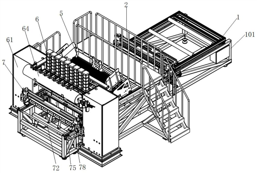
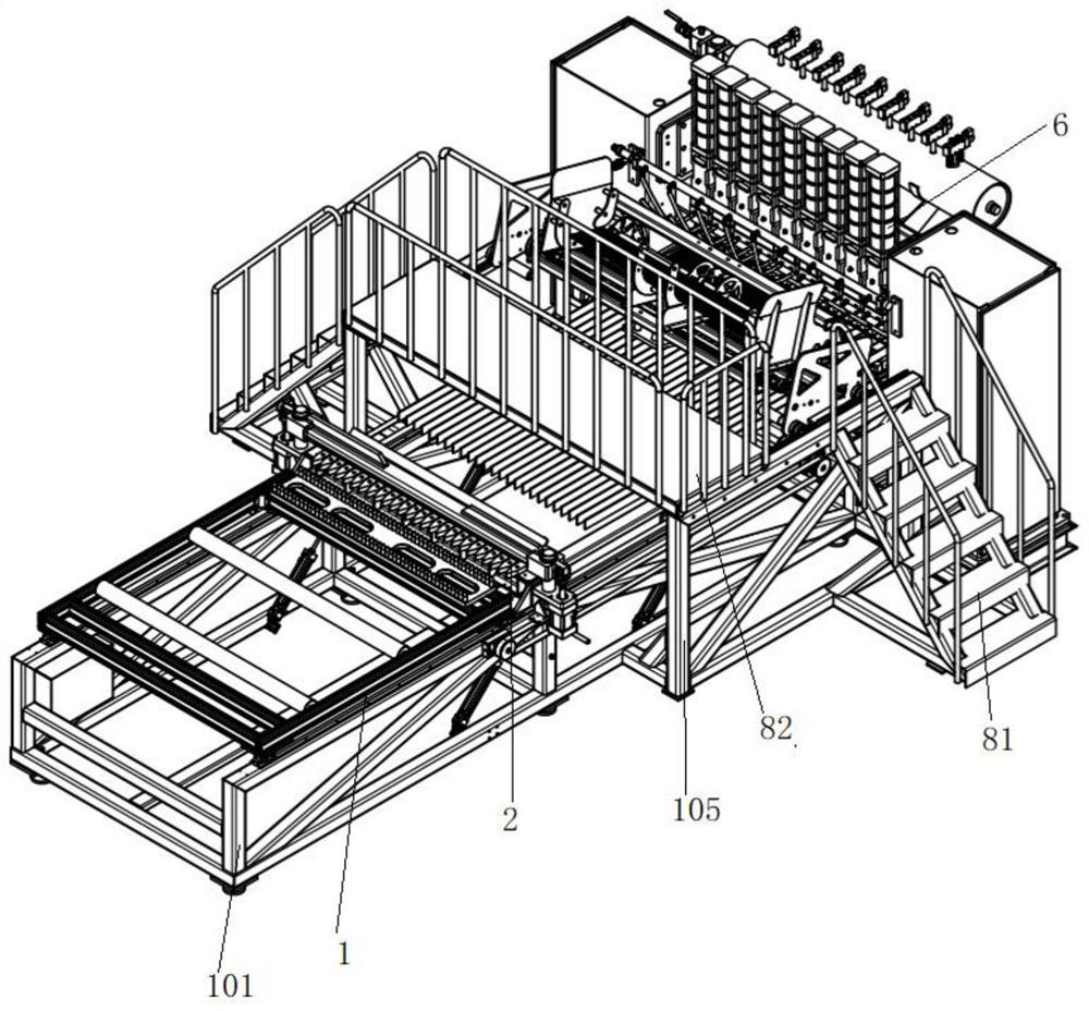
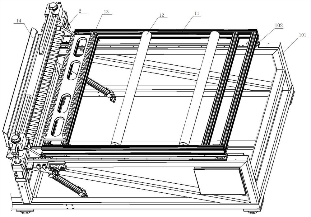
The invention discloses an intelligent cross rod pressure welding device integrating feeding, machining and discharging, which comprises a conveying mechanism, a feeding clamping mechanism, a feeding clamping mechanism, a cross rod feeding mechanism, a welding mechanism and a discharging mechanism, and the conveying mechanism, the feeding clamping mechanism and the feeding clamping mechanism are all arranged on a conveying rack; the feeding clamping mechanism is arranged on the feeding rack, the transverse rod feeding mechanism is arranged on the feeding rack, the transverse rod feeding mechanism is arranged above the feeding clamping mechanism, the welding mechanism is arranged between the feeding clamping mechanism and the discharging mechanism, and the discharging mechanism is arranged on the discharging rack. Automatic feeding of flat steel is achieved through mutual cooperation of the conveying mechanism, the feeding clamping mechanism and the supply clamping mechanism, automatic feeding of transverse rods is achieved through the transverse rod feeding mechanism, selective welding is conducted on the intersection of the flat steel and the transverse rods through the welding mechanism, finished products are automatically taken out through the discharging mechanism, and the production efficiency is improved. And automation and intelligentization are truly achieved from feeding to welding to discharging, the manual labor amount is reduced, and the production efficiency is improved.
Description
technical field [0001] The invention belongs to the field of advanced manufacturing technology, and in particular relates to an intelligent horizontal bar pressure-welding equipment integrating feeding, processing and discharging and a working method thereof. Background technique [0002] The steel grating is a kind of steel product that is cross-arranged with flat steel according to a certain distance and cross bars (twisted, square steel, round steel, flat steel, etc.), and welded into a square grid in the middle. The steel grating is mainly It is used to make gutter cover, steel structure platform board, steel ladder step board, etc. The cross bar is generally made of twisted square steel, and the steel grating is generally made of carbon steel. The appearance is hot-dip galvanized to prevent oxidation. role. It can also be made of stainless steel. The steel grating has ventilation, lighting, heat dissipation, anti-skid, explosion-proof and other properties. [0003] Du...
Claims
Login to View More Application Information
Patent Timeline
 Patent Type & AuthorityApplications(China)
IPC IPC(8): B23K37/00B23K31/02
CPCB23K37/00B23K31/02
Inventor张敏强
Owner苏州鹄珂智能科技有限公司