Fruit tree pollination device for kiwi fruits

A pollination device and kiwifruit technology, applied in the application, plant genetic improvement, agriculture and other directions, can solve the problems of difficult kiwifruit style spraying, low spraying efficiency, artificial height limitation, etc., to solve the problem of uncontrollable grant amount, improve pollination efficiency, guarantee The effect of uniformity

Pending Publication Date: 2022-06-24
麻阳蓝凤凰农业发展有限公司
View PDF1 Cites 1 Cited by
  • Summary
  • Abstract
  • Description
  • Claims
  • Application Information

AI Technical Summary

Problems solved by technology

[0004] The existing pollination device for kiwifruit fruit trees requires manual lifting to spray each kiwifruit style. Long-term lifting will make the arms feel sore, resulting in low spraying efficiency, and the artificial height is limited, so it is not easy to spray the higher kiwifruit. The style is sprayed, which causes the unsprayed kiwifruit style to fail to bear intact fruit, which reduces the fruiting rate and fruit quality of the kiwi fruit tree

Method used


Image

  • Fruit tree pollination device for kiwi fruits
  • Fruit tree pollination device for kiwi fruits
  • Fruit tree pollination device for kiwi fruits

Examples


Embodiment 1

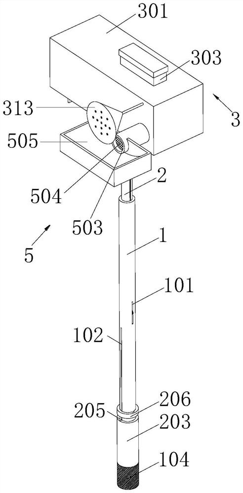
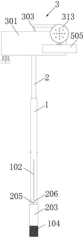
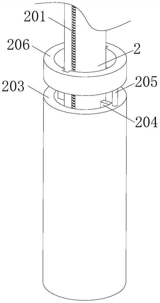
[0029] Example 1, please refer to Figure 1-6 , a fruit tree pollination device for kiwifruit, comprising a sliding cylinder 1 and a No. 1 strip hole 101 symmetrically opened at the left and right ends of the outer wall of the sliding cylinder 1, the No. 1 strip hole 101 is communicated with the interior of the sliding cylinder 1, and the outer wall of the sliding cylinder 1 And located below the No. 1 strip hole 101 is symmetrically opened with a No. 2 strip hole 102, the No. 1 strip hole 101 and the No. 2 strip hole 102 are arranged in a cross-shaped array along the outer wall of the sliding cylinder 1. A fixed rod 103 is symmetrically arranged at the bottom end of the rod 101 corresponding to the position of the No. 1 strip hole 101. The bottom ends of the two fixed rods 103 are fixedly connected with a handle 104. The diameter of the handle 104 is larger than the outer diameter of the sliding cylinder 1. The outer wall of the handle 104 Covered with a non-slip film, a tele...

Embodiment 2

[0031] Example 2, please refer to Figure 1-2 And 7-10, on the basis of Embodiment 1, the top of the telescopic rod 2 is provided with a screeding mechanism 3, and the screeding mechanism 3 includes a storage box 301 fixedly connected to the top of the telescopic rod 2, the front and rear of the inner wall of the storage box 301 A partition 302 is fixedly connected between the two ends, the top of the storage box 301 is provided with a powder injection port 303, and a bottom plate 304 is connected between one side of the partition 302 and the inner wall of the storage box 301. A side plate 305 is symmetrically arranged on the side of the end and away from the side plate 302, and there is a gap between the two side plates 305. 306 is located between the two side plates 305 and is not in contact with the side plates 305. The top end of the inner wall of the storage box 301 is provided with a scraper 307. There is a gap between the bottom end of the scraper 307 and the top of the...

Embodiment 3

[0033] Example three, please refer to Figure 7-8 , on the basis of the second embodiment, the inside of the storage box 301 is provided with a spraying mechanism 4, and the spraying mechanism 4 includes a piston plate 401 that is slidably fitted inside the storage box 301 and is located on one side of the partition 302. The top corresponding to the position between the partition plate 302 and the piston plate 401 is provided with an air inlet, the side wall of the piston plate 401 is provided with an air intake pipe 402, and the end of the air intake pipe 402 away from the piston plate 401 sequentially penetrates the side wall of the partition plate 302 and the At the rear end of the storage box 301, a first check valve 403 is provided at the end of the intake pipe 402 close to the piston plate 401, and an exhaust hole is provided on the side wall of the partition plate 302 and above the intake pipe 402. A first exhaust pipe 404 is disposed on the side of the wall close to th...


PUM


Abstract

The fruit tree pollination device comprises a sliding barrel and fixing rods symmetrically arranged at the bottom end of the sliding barrel, the bottom ends of the two fixing rods are jointly and fixedly connected with a handle, a telescopic rod is arranged in the sliding barrel in a sliding fit mode, and a material uniformizing mechanism, a spraying mechanism and a collecting mechanism are arranged at the top of the telescopic rod; by manually pulling the sleeve, the telescopic rod moves up and down according to the position of a kiwi fruit stylus in the pollination process and can be rapidly and stably stretched and shortened, the pollination efficiency is improved, the production capacity of an orchard is improved, the spraying uniformity of kiwi fruit pollen is guaranteed through the material uniformizing mechanism, and the pollination efficiency is improved. Quantitative pollination of kiwi fruits is achieved, the problem that in the prior art, the pollination amount of kiwi fruit pollen is uncontrollable is solved, the inclined face of the wedge-shaped block can prevent the kiwi fruit pollen from being damped and agglomerated due to long-term accumulation, and therefore spraying of the kiwi fruit pollen is improved.

Description

technical field [0001] The invention relates to the field of kiwifruit planting, in particular to a fruit tree pollination device for kiwifruit. Background technique [0002] The kiwi is a dioecious plant, with both males and females producing pollen, but the pollen of female plants is usually inactive and only male plants can produce viable pollen, so they must pollinate between male and female plants. The methods of kiwifruit pollination include insect pollination and artificial pollination. The artificial pollination of kiwifruit is to use a small brush or pollination device to lightly apply pollen on the stigma of the female flower. [0003] Chinese Patent Publication No. CN 206760361 U, the application relates to a kiwifruit pollination device, and relates to the field of kiwifruit planting, including a pollinator, one side of the pollinator is provided with a gas injection pipe perpendicular to it, and a piston and a gas injection pipe are arranged in the gas injection...

Claims


Application Information

Patent Timeline
Patent Type & Authority Applications(China)
IPC IPC(8): A01H1/02
CPCA01H1/027
Inventor 贾建文王玉宇雷华英
Owner 麻阳蓝凤凰农业发展有限公司
Why Eureka
Try Eureka