Automatic pipe welding machine and dust removal mechanism thereof

An automatic welding and pipe machine technology, applied to welding equipment, welding equipment, tubular objects, etc., can solve the problems of time-consuming, unsatisfactory rust removal effect, etc., and achieve the effect of improving production efficiency and ensuring dust removal effect

Active Publication Date: 2022-06-24
扬州万丰机械制造有限公司
View PDF8 Cites 2 Cited by
  • Summary
  • Abstract
  • Description
  • Claims
  • Application Information

AI Technical Summary

Problems solved by technology

[0005] The object of the present invention is to provide an automatic pipe welding machine and its dedusting mechanism to solve the problem of transporting pipelines back and forth between the dedusting machine and the pipe welding machine proposed in the above background technology, which takes a lot of time, and the dedusting mechanism in the prior art usually uses Dust is removed by blowing, which can easily blow up dust and small oxide scales, but the effect of removing stubborn rust is not ideal

Method used


Image

  • Automatic pipe welding machine and dust removal mechanism thereof
  • Automatic pipe welding machine and dust removal mechanism thereof
  • Automatic pipe welding machine and dust removal mechanism thereof

Examples


specific Embodiment approach 1

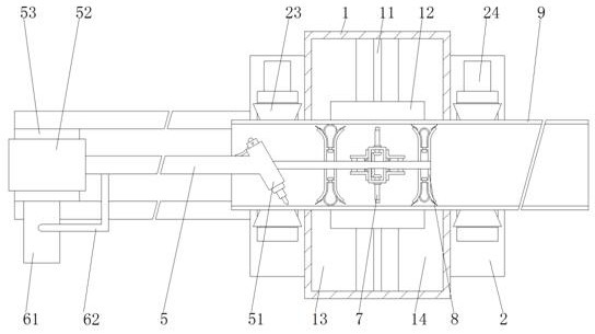
[0036] Specific implementation mode 1: Please refer to Figure 1-6 , the first aspect of the present invention: a dust removal mechanism of an automatic pipe welding machine, comprising:

[0037] The collection box 1 is placed on the base 2, the left and right sides of the collection box 1 are symmetrically provided with openings 15, the inner bottom end of the collection box 1 is fixed with a partition 11, and the top surface of the partition 11 is hingedly installed with a guide plate 12;

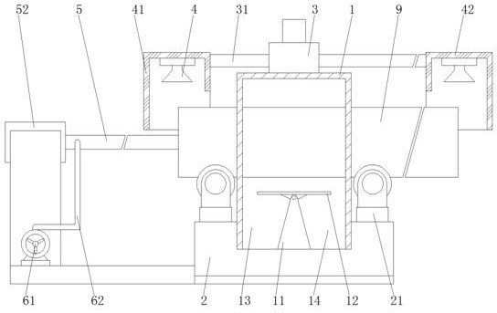
[0038] The top seat 3 is arranged on the top surface of the collecting box 1, and a guide rail 31 is inserted into the top seat 3, and the two ends of the guide rail 31 are respectively connected to the left air collecting box 41 and the right air collecting box 42;

[0039] The air extraction head 4, the left air collection box 41 and the right air collection box 42 are evenly installed with the air extraction head 4;

[0040] The gas delivery pipe 6, the right end of the gas delivery p...

specific Embodiment approach 2

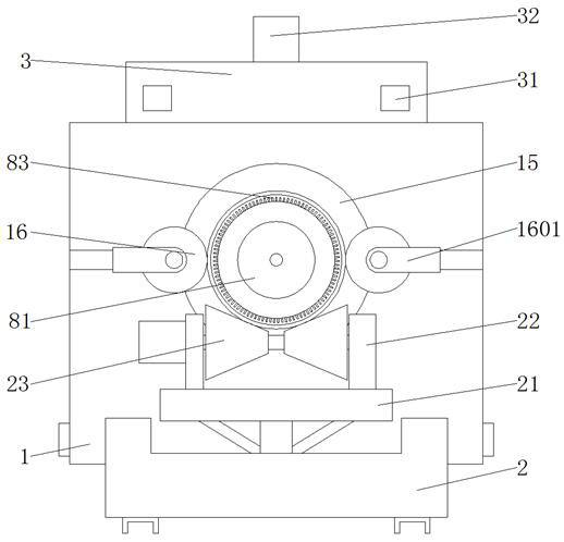
[0043] Embodiment 2: This embodiment is a further limitation of Embodiment 1, such as figure 1 and image 3As shown, limit wheels 16 are installed on the left and right sides of the collection box 1. There are four limit wheels 16 in total. A connecting plate 1601 is installed on the outer side of the limit wheel 16, and the other end of the connecting plate 1601 is fixedly connected. Abutting block 1602, the abutting block 1602 enters the collection box 1 through the chute 1603, the chute 1603 is symmetrically distributed about the opening 15, the collection box 1 is used to collect solid large particles of debris, the solder tank 13 and the waste slag tank 14 are close to each other. The openings 15 on the left and right sides of the collection box 1 realize separate collection, which is convenient for subsequent recycling and reuse.

specific Embodiment approach 3

[0044] Embodiment 3: This embodiment is a further limitation of Embodiment 2, such as Figure 4 As shown, an isosceles triangle-shaped partition 11 is fixed in the middle of the bottom surface of the collecting box 1. The partition 11 separates the bottom space of the collecting box 1 to form a solder tank 13 and a waste slag tank 14. The solder tank 13 is close to the welding gun 51, and the solder tank 13 and A rotating shaft 18 is installed in the waste slag tank 14. The rotating shaft 18 is sleeved with a long rod 17 and a short rod 19. The long rod 17 and the short rod 19 are in contact with the abutment block 1602 and the guide plate 12 respectively. The long rod 17 and the short rod 19 rotates around the rotating shaft 18, when the abutting block 1602 pushes the long rod 17, the short rod 19 lifts the guide plate 12 upward, and the short rod 19 is fixed with a counterweight block, when the abutting block 1602 is reset, the short rod 19 is in the The action of gravity ro...


PUM


Abstract

The invention discloses an automatic pipe welding machine and a dust removal mechanism thereof, and the dust removal mechanism comprises a collection box placed on a base, and openings are symmetrically formed in the left surface and the right surface of the collection box; the top seat is arranged on the top surface of the collecting box; the air exhaust heads are uniformly mounted in the left air collection tank and the right air collection tank; the right end of the gas conveying pipe is horizontally inserted into the opening, and the gas conveying pipe is sleeved with a purging head and a partition piece; the purging head comprises a round box, an air nozzle and a sleeve; the partition pieces are symmetrically distributed on the left side and the right side of the blowing head, and each partition piece comprises a disc, an air bag and bristles. According to the automatic pipe welding machine and the dust removal mechanism thereof, the gas conveying pipe is sleeved with the fixing pipe, the welding part is installed on the fixing pipe, and the dust removal part is installed on the gas conveying pipe, so that dust removal and welding operation can be conducted on the welded pipe at the same time, the production efficiency is improved, the pipe wall is brushed through the bristles made of metal materials, and attachments on the pipe wall are effectively removed.

Description

technical field [0001] The invention relates to the related technical field of pipeline welding dust removal, in particular to an automatic pipe welding machine and a dust removal mechanism thereof. Background technique [0002] In the production process of straight seam submerged arc welded pipe, the steel plate is formed by milling, pre-bending, forming and welding. Welding can easily affect the welding quality, and at the same time, the mixing of these foreign substances into the flux will increase the difficulty of flux recycling. [0003] In the prior art, the pipeline is usually sent to the dust collector for dust removal operation, and then the pipeline is sent to the pipe welding machine for welding operation after creating a good welding environment. Time, and the dust removal mechanism in the prior art usually adopts a purging method to remove dust, which can easily blow up dust and small oxide scale, but the removal effect of stubborn rust is not ideal. SUMMARY...

Claims


Application Information

Patent Timeline
Patent Type & Authority Applications(China)
IPC IPC(8): B23K31/02B23K37/00
CPCB23K31/027B23K37/00B23K2101/06Y02P70/10
Inventor 朱伟
Owner 扬州万丰机械制造有限公司
Why Eureka
Try Eureka